Evaluation of mechanical properties of esthetic brackets
- 1Division of Orthodontics, Department of Human Development and Fostering, School of Dentistry, Meikai University, Saitama, Japan
- 2Department of Mechanical Engineering, Nippon Institute of Technology, Saitama, Japan
- 3Division of Pedodontics, Department of Human Development and Fostering, School of Dentistry, Meikai University, Saitama, Japan
- Shigeyuki Matsui, Division of Orthodontics, Department of Human Development and Fostering, School of Dentistry, Meikai University, Keyakidai 1-1, Sakado, Saitama 350-0248, Japan. Email: matsui{at}dent.meikai.ac.jp
Abstract
Plastic brackets, as well as ceramic brackets, are used in various cases since they have excellent esthetics. However, their mechanical properties remain uncertain. The purpose of this study was to determine how deformation and stress distribution in esthetic brackets differ among materials under the same wire load. Using the digital image correlation method, we discovered the following: (1) the strain of the wings of plastic brackets is within 0.2% and that of ceramic and metal brackets is negligible, (2) polycarbonate brackets having a stainless steel slot show significantly smaller displacement than other plastic brackets, and (3) there is a significant difference between plastic brackets and ceramic and stainless steel brackets in terms of the displacement of the bracket wing.
Introduction
In daily orthodontic practice, the most important requirement to ensure the effective movement of teeth is to understand the force and moment generated by orthodontic appliances. Previous studies on the biomechanics of tooth movement and the appliance-generated force can be roughly divided into theoretical analysis1 and experimental analysis.2 Theoretical analysis generally involves the finite element method,1 while experimental analysis includes the strain gauge method,3 photoelastic investigation,4 electronic speckle pattern interferometry (ESPI),5 and digital image correlation.2,6
Many studies on the biomechanics occurring between a wire and bracket have focused on changes in the friction, torque, and moment. Meanwhile, most studies on the deformation of brackets under wire loading are based on the finite element method, which is a method of numerical analysis. When using the same wire, brackets with different compositions are expected to exhibit different deformation states and stress distributions, resulting in different distributions of the force transmitted to the periodontal ligament. Therefore, bracket deformation is an important factor affecting the force system in orthodontic treatment.
For objects having a relatively simple structure and objects made of a single isotropic material, no significant differences are expected between actual results and the results of analysis by the finite element method. However, for objects having a complex structure, such as orthodontic brackets, there is a limit to the accuracy of finite element modeling,7,8 and it is desirable to conduct experiments using actual brackets. Nevertheless, brackets are too small to be used as test specimens, making it impossible to obtain an area that is sufficiently large to determine deformation and distortion by contact measurement, such as by the strain gauge method or brittle lacquer coating method.
In recent years, as a method of experimental analysis, the non-contact displacement measurement of various objects has been reported in the engineering field owing to the development of the digital image correlation method.2,3 This method captures a digital image of a sample before and after a load is applied and then tracks a random pattern applied on the sample surface to determine the deformation during the test. Samples of various sizes from test pieces of millimeter order to huge structures such as bridges can be experimentally analyzed using charge-coupled device (CCD) cameras. In the field of orthodontics, deformation has been measured by this method after applying torque from a wire to a stainless steel bracket.2 However, deformation has not been measured for esthetic brackets, such as ceramic brackets and plastic brackets, which have become popular in recent years.
Digital image correlation was used in this study to evaluate the differences in the deformation and stress distribution between different types of esthetic brackets under the same wire load.
Materials and methods
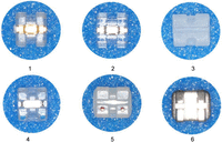
As experimental materials, we used four types of plastic brackets (Code Nos 1–4) and a ceramic bracket (Code No. 5) measuring 0.018 × 0.025 in, all of which were commercially available. A stainless steel bracket (Code No. 6) was used for comparison. Eight samples were used for each bracket. Table 1 shows the six types of brackets and Figure 1 shows their appearance. Three of the four types of plastic brackets have stainless steel–reinforced slots. A test specimen consisted of a bracket, orthodontic wire, elastic ring, and aluminum base. The bracket was bonded to a 15-mm-thick aluminum plate using Araldite® adhesive, which hardens completely in 24 h. Before bonding each bracket to the aluminum base, we calculated the area of the base of the bracket. Next, we determined the bonding load to ensure a constant bonding pressure per unit area and applied the load perpendicular to the bracket base using a load cell to bond the bracket using Araldite. Then, we formed a random pattern on the bracket wing by applying a white acrylic spray paint to the surface, allowing it to dry completely, and then applying a black spray paint using an air brush.
Each bracket used in this study.
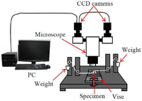
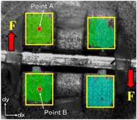
Figure 2 shows a diagram of the experimental apparatus, and Figure 3 shows how the load F was applied to the orthodontic wire (0.018 × 0.025 in) as well as the area where the deformation of the bracket and the extent of slot opening were determined by the digital image correlation method. To apply the load, a steel load wire (0.28 mm in diameter) was connected to each end of the orthodontic wire, which was processed into a hook shape, the load wire was run through a pulley, and a weight was placed on a pan that was attached to the end of the load wire. To apply a moment M to the bracket, we applied a load F of 2 N to both ends of the wire inserted into the bracket (the distance between both ends was 13.2 mm) in opposite directions. Thus, the moment M was 2 N × 13.2 mm = 26.4 N mm.
Directions of forces (F) acting on orthodontic wire. Points A and B were set for measuring displacement and to determine opening of slot.
We measured the displacement, strain, and von Mises stress in the x- and y-directions when a load of 2 N was applied. The extent of slot opening of the bracket was calculated from the average vertical displacement of an area of 25 × 25 pixels in the center of bracket wings A and B. The displacement of the bracket was obtained as the average displacement of bracket wing A for each load, which was increased in steps of 0.5 N. We used a Vic-3D Micro™ system (Correlated Solutions Inc., USA) for the experiment. We captured images of the brackets using two CCD cameras and analyzed the images using three-dimensional digital correlation software (Vic-3D 2012; Correlated Solutions Inc.). The spatial resolution was 6.0 µm/pixel and the correlation area was automatically set to 27 × 27 pixels. In this study, we determined the displacement in two directions, the strain, and the increase in slot width using digital image correlation processing software (VEDDAC2.6; Ettemeyer, Germany). Analysis of variance (ANOVA)/Scheffé’s method (SPSS ver 19.0; IBM, Japan) was used to determine the significance of differences in mean measured values among the brackets.
Results
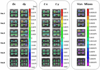
Figure 4 shows the displacement, strain, and von Mises stress on the brackets under a moment load. All the plastic brackets (Code Nos 1–4) showed a maximum displacement of the loaded wing of 0.005–0.017 mm in the y-direction. Code Nos 1 and 2 showed a relatively large strain and von Mises stress. The strain of the two wings on the bracket was within 0.2% for the plastic brackets and negligible for the ceramic and stainless steel brackets. There was no significant difference in the strain of the bracket wing among the plastic, ceramic, and stainless steel brackets, but the plastic brackets showed a large displacement, which we considered to be due to the deformation of the plastic bracket above the base.
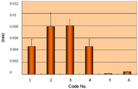
Figure 5 shows the increase in the slot width caused by the moment load. All the plastic brackets exhibited displacement of the loaded wing accompanied by an increase in the slot width. The polycarbonate brackets (Code No. 1) showed an increase in the slot width of 0.003–0.006 mm on both sides. The polyamide brackets and polyurethane brackets (Codes Nos 2 and 3, respectively) showed an increase of 0.006–0.01 mm, and the brackets made of a mixtures of polycarbonate and polyethylene terephthalate (Code No. 4) showed an increase of 0.003–0.006 mm. Among the brackets reinforced with stainless steel slots, there was a significant difference of approximately 5% between Code Nos 1 and 4 and Code No. 3, but no significant difference was found between Code Nos 2 and 3. These results indicate that plastic brackets, including polycarbonate ones, reinforced with a stainless steel slot, are significantly more rigid against moment loads than plastic brackets made of polyurethane and polyamide.
The ceramic and stainless steel brackets hardly showed any increase in slot width. The increase was 0.15 µm for the ceramic brackets (Code No. 5) and 0.43 µm for the stainless steel brackets (Code No. 6). These increases are approximately 1/70–1/20 of the increases observed for the plastic brackets.
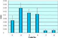
On the other hand, the polyamide brackets showed the largest displacement of the bracket wing, which was 0.014 mm on average (Figure 6), despite the stainless steel–reinforced slots. Among the plastic brackets, Code No. 1 showed the smallest displacement of 0.007 mm on average, which is about half that of the other plastic brackets. No significant difference was found among the plastic brackets except for Code No. 1, even though they differed in structure and composition.
Meanwhile, the displacement of the wings of the ceramic brackets and stainless steel brackets was lower than 0.002 mm. This is approximately 1/14–1/7 of the displacement observed in the plastic brackets.
Discussion
Analysis method used in this study
The digital image correlation method was employed for the mechanical analysis of the brackets in this study. This method is used for displacement analysis to determine the deformation state of objects.9 It is widely adopted in the engineering field because it allows easy visual understanding and does not require any special equipment or operations to analyze displacement, owing to its ability to track specific points by image analysis. The location and extent of deformation can be easily understood in detail from the vector representation of displacement obtained by this method. Furthermore, by increasing the magnification using a stereo microscope, it is possible to analyze the infinitesimal deformation of extremely fine structures. The measurement principle is to compare two digital grayscale images and track specific points on one image on the other image based on the brightness (gray value) of each pixel in the images. Once a correlation is found for such specific points, the displacement and distance can be measured. Thus, it is not necessary to define any measuring points or reference lines in this method. The deformation and strain of any part can be determined from the image of a random pattern without touching the object. Therefore, we considered this method to be highly effective for evaluating the deformation state of brackets, which are small and have a complex force system.
Physical properties of plastic brackets
The first esthetic brackets were plastic brackets made of acryl and then polycarbonate. However, there were many problems with early plastic brackets, such as coloration, lack of bond strength, breakage of ligation wings, and permanent deformation. To overcome the shortcomings of esthetic brackets made of polycarbonate alone, various measures were devised, such as blending ceramic and fiberglass into the polycarbonate and incorporating metal slots. Also, high-quality polyurethane was used for the production of brackets. Although there are some problems such as slight opening of the slot due to torque, polycarbonate brackets with a metal-reinforced slot exhibit less creep than the early polycarbonate brackets.10 Also, ceramic or metal-reinforced polycarbonate brackets show torque loss of approximately 15% after 24 h.11 Sadat-Khonsari et al.12 compared stainless steel brackets and plastic brackets in terms of the deformation caused by torque and reported that plastic brackets with a metal-reinforced slot showed the smallest deformation and ceramic-reinforced polycarbonate brackets showed the largest deformation. They concluded that the stability of polycarbonate brackets against torque was not improved by the addition of ceramic or fiberglass, and no difference was found between pure polyurethane brackets and pure polycarbonate brackets within the optimum torque range. Another study evaluated the resistance of esthetic brackets against deformation and fracture caused by wire distortion.13 This study reported that plastic brackets mixed with ceramic and reinforced with a stainless steel slot showed the highest resistance against deformation, and pure polycarbonate brackets showed the lowest resistance. The authors concluded that the mixing of ceramic filler did not increase the bracket strength.
Feldner et al.11 reported that the torque moment of polycarbonate brackets was attenuated by Sadat-Khonsari et al.12 to 15% by creep. Therefore, they suggested that it is necessary to apply additional torque to the wire to obtain the intended torque in the clinical use of polycarbonate brackets.
In this study, plastic brackets including polycarbonate material showed significant differences in the slot width (Figure 5). It is suggested that polycarbonate brackets reinforced with a stainless steel slot are particularly rigid against moments. Regarding the displacement of the entire bracket, however, only the pure polycarbonate brackets reinforced with a stainless steel slot showed significantly smaller displacement than the other plastic brackets (Figure 6).
Furthermore, within each bracket type, the bracket width (Figure 5) was always greater than the displacement of the bracket wings (Figure 6). This suggests that deformation occurred not only at the bracket wings but also at the bracket base when a load was applied.
Physical properties of ceramic brackets
Ceramic brackets were introduced to overcome the shortcomings of plastic brackets. Ceramic brackets have a high degree of freedom in their design owing to their manufacturing process. Therefore, various types of ceramic brackets are available depending on the orthodontic treatment technique. Ceramic brackets have high rigidity and abrasion resistance as well as stable properties and they are free from coloration. In this study, ceramic brackets showed highly stable properties compared with plastic brackets and similar resistance against moment loads to stainless steel brackets.
However, there still remains a problem with debonding. Initially, ceramic brackets were bonded using a silane coupling agent since they cannot be chemically bonded with adhesives. However, the silane coupling was so strong that debonding frequently caused the peeling of enamel or cracking. Stainless steel brackets and plastic brackets can be safely removed from the tooth surface by distorting the bracket base. However, ceramic brackets do not plastically deform but instead break and leave fragments on the tooth surface, which makes debonding difficult. In recent years, mechanical engagement using light-polymerized resin has been attempted to limit the adhesion strength and reduce the problem of debonding, but debonding still requires careful attention compared with the debonding of brackets made of other materials.
In addition, ceramic brackets are broken by a force greater than a certain level while plastic brackets are reversibly or plastically deformed. Nishio et al.13 reported that ceramic brackets showed significantly higher deformation resistance than plastic brackets and, in particular, ceramic brackets reinforced with a stainless steel slot showed the highest resistance. On the other hand, they reported that the part most frequently broken by applying a force greater than a certain level was the wing on the incisal side of brackets made of ceramic alone and that the breakage does not depend on the bracket size and is mainly caused by the non-reinforced slot. The ceramic brackets used in this study were made of ceramic alone and were not reinforced with stainless steel slots, but they were not broken under the loading conditions of the experiment. However, in clinical situations, especially when using a rectangular wire, such conditions often occur. Therefore, we consider that further experiments should be conducted under loading conditions simulating torque.
In this study, we observed the deformation of brackets at their elastic limit, but there have also been studies on the plastic deformation of brackets. Lacoursiere et al.14 observed the deformation state of a bracket wing using the digital image correlation method when lingual root torque was applied to a stainless steel bracket. They reported that a high rate of elastic deformation was observed after the release of the torque, but slight plastic deformation was also observed. As revealed by this study, ceramic brackets have higher rigidity than stainless steel brackets. Therefore, the plastic deformation of ceramic brackets is considered to be less than that of stainless steel brackets. The force from the wire may be attenuated to some extent by plastic brackets and stainless steel brackets, but highly rigid ceramic brackets are expected to transmit the force from the wire to the teeth without the deformation of the brackets. However, there is concern about the frictional resistance of the slot and abrasion of the enamel of the opposing tooth because of the high rigidity and abrasion resistance of ceramic brackets.
Esthetic brackets have both advantages and disadvantages; therefore, some clinicians still believe that there are no brackets with physical properties superior to those of stainless steel brackets. However, the demand for esthetic brackets, especially by adult patients, is expected to continue to increase. Therefore, the clinician should become familiar with the nature of each type of esthetic bracket before its clinical application.
Conclusion
We determined the displacement and strain of brackets under a moment load using the digital image correlation method, which is a non-contact displacement measurement system and discovered the following:
-
The strain of the wings of plastic brackets is within 0.2% and that of ceramic and metal brackets is negligible.
-
Polycarbonate brackets having a stainless steel slot show significantly smaller displacement than other plastic brackets.
-
There is a significant difference between plastic brackets and ceramic and stainless steel brackets in terms of the displacement of the bracket wing.
Article Notes
-
Declaration of conflicting interests The authors declare that there is no conflict of interest.
-
Funding This research received no specific grant from any funding agency in the public, commercial, or not-for-profit sectors.
- Received October 14, 2014.
- Accepted January 25, 2015.
- © The Author(s) 2015
This article is distributed under the terms of the Creative Commons Attribution-NonCommercial 3.0 License (http://www.creativecommons.org/licenses/by-nc/3.0/) which permits non-commercial use, reproduction and distribution of the work without further permission provided the original work is attributed as specified on the SAGE and Open Access page (http://www.uk.sagepub.com/aboutus/openaccess.htm).

