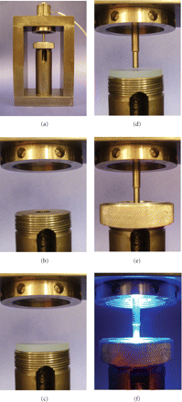
Controlled compliance apparatus for contraction stress test. (a) The entire apparatus with a view of the steel frame and the upper load cell holder; (b) slot for light guide; (c) glass plate positioned; (d) steel piston in position and the space where the resin-composite specimen is positioned; (e) equipment ready for use; (f) light curing procedure during the experiment. These pictures were kindly donated by Dr. Carmen Silvia C. Pfeifer. Equipment is from Division of Biomaterials and Biomechanics, the School of Dentistry, Oregon Health & Sciences University (Portland, USA).


