|
 
 |
| REVIEW ARTICLE |
|
| Year : 2016 | Volume
: 4
| Issue : 1 | Page : 1-7 |
|
Rapid prototyping: A future in orthodontics
Avinash Kumar, Hajra Ghafoor
Department of Orthodontics, Al-Badar Rural Dental College and Hospital, Gulbarga, Karnataka, India
| Date of Web Publication | 5-Apr-2016 |
Correspondence Address:
Avinash Kumar
Department of Orthodontics, Al-Badar Rural Dental College and Hospital, Gulbarga, Karnataka
India
 Source of Support: None, Conflict of Interest: None  | Check |
DOI: 10.4103/2321-3825.167856

Rapid prototyping (RP) is the name given to the host of related techniques that are used to fabricate the physical models based on computer-aided design and computer-aided manufacturing. RP technology allows the building of a medical model layer by layer, reproducing almost every form of the external and internal anatomic structure. It has rapid speed, better design communication, and easy detection of flaws. Data for RP is obtained from the magnetic resonance image/computed tomography scan slice images and they are converted into digital image which in turn is transformed to standard triangulation language file and afterward layer by layer construction is done by different techniques such as stereolithography, fused deposit modeling, selective laser sintering and inkjet printing to form the physical model. The applications of this digital technology in orthodontics includes diagnosis and treatment planning, fabrication of orthodontic removable appliances, impression trays for indirect bonding, and surgical template for implant placement, prototype model is employed in various orthognathic surgeries, it has been used for the custom manufacture of lingual orthodontics appliances and also to produce a distractor during distraction osteogenesis. Its advantages include rapid fabrication, minimal time, easy handling, better visualization, reuse of design, and repeated verification, however, the clinical judgment still remains vital. This article reviews the use of RP in the field of orthodontics; it improves a valuable insight at the time of preoperative treatment planning and enhances the quality of treatment effect. There is a divergence in the applications of RP for an orthodontist, and the future looks more promising if we use it innovatively. Keywords: Digital technologies, orthodontics, rapid prototyping, stereolithography
How to cite this article:
Kumar A, Ghafoor H. Rapid prototyping: A future in orthodontics. J Orthod Res 2016;4:1-7 |
| Introduction | |  |
Rapid prototyping (RP) broadly indicates the fabrication of a three-dimensional (3D) model from a computer-aided design (CAD), traditionally built layer by layer according to the 3D input. [1] The technology was first introduced in mechanical engineering, and is mainly used to evaluate the ease of assembly and manufacture of designed products ahead of actual production. Recently, the area of application has widened into other fields, including medicine. [2] Many applications in medicine have become possible due to the convergence of three distinct technologies namely, medical imaging, computer graphics/CAD, and RP. [1],[2],[3] The first commercial process of RP was presented at the Autofact show in Detroit (US) in November 1987 by a company called 3D systems, Inc. At that time, the process was very inaccurate, and the choice of materials was limited. Therefore, the parts obtained were considered prototypes. As in software engineering, a prototype is something to look at, serves as a basis for discussion, but cannot be used for anything "serious," that is, in a production environment.
RP technology allows the building of a medical model layer by layer, reproducing almost every form of the external and internal anatomic structure. It has rapid speed, better design communication, and easy detection of flaws. [3] To fabricate a physical prototype (model) in industry and/or medicine, two different approaches have been utilized; subtractive and additive. [4],[5] The subtractive technique is usually accomplished by the computer numerically controlled (CNC) machining, generally milling. [5] The additive technologies, on the other hand, can produce arbitrarily complex shapes with cavities, which is usually the case in human anatomy structures. The key idea of this innovative method which is also called "layered manufacturing" or "solid free form fabrication" is that a solid 3D CAD model of an object decomposed into the cross-sectional layer representations and then numerical files in the form of virtual trajectories guiding material additive processes for physically rapid building up of these layers in an automated fabrication machine to form the object called the prototype. [6]
Creating a rapid prototype involves a number of steps that must be accomplished before the 3D model is formed. These "3D" printers allow the designers to quickly create tangible prototypes of their designs, rather than just two-dimensional photographs. This development was supported by the capability of modern imaging modalities, such as spiral computed tomography (CT) or magnetic resonance image (MRI), to produce continuous volumetric data sets, which provide the input data for model generation. [7],[8]
RP is used in dentistry for a range of dental specialties, including oral surgery and implantology, [2],[9] operative dentistry, [9] prosthodontics, [10] and orthodontics. [2],[7],[9] Significant advancements in this technology have now resulted in their commercial availability with shorter clinical protocols. [10] The key objective of this review is to focus on the latest advancements in RP and its applications in the field of orthodontics.
| Process of Fabrication | | |
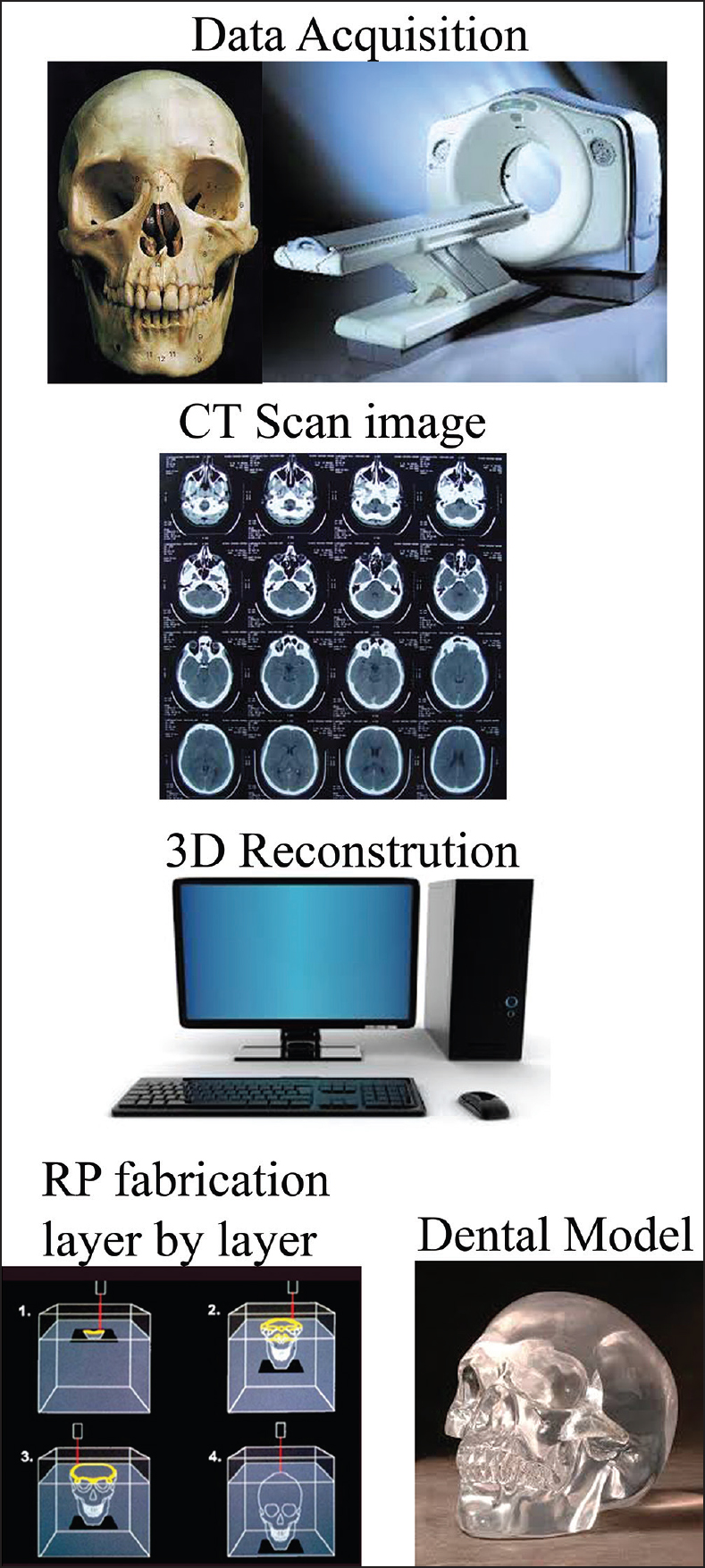
RP additive nature allows it to create objects with complicated internal features and external morphology that cannot be manufactured by other means. [3] Data is obtained from MRI/CT scan slice images. It is exciting that in spite of the availability of CT scanners since 1973, [11] it was not until 1987 that this innovative technology became available for dental application. [12] Scan data are presented in a layer by layer format, [7] these are then converted into a digital image which in turn is transformed to standard triangulation language (STL) file. Software packages "slices" the CAD model into a number of thin (-0.1 mm) layers, which are then build up one on top of another as explained in [Figure 1]. This process produces highly accurate models with an excellent surface finish. Photopolymer materials were used earlier but had limitations such as brittleness and property changes with humidity and temperature and so, new epoxy made polymers have evolved. [3]
Types
RP has taken enormous strides after detection. Nowadays, there are over 30 processes, some of which are commercial, and the rest are underdeveloped. However, the accuracy has improved significantly. [3] Four methods are widely used in dentistry, [7] they are:
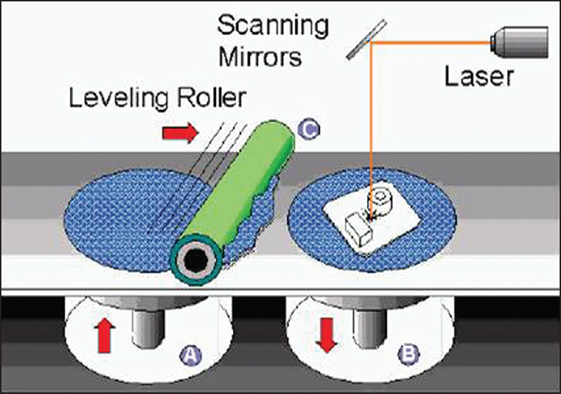
Stereolithography
Due to its accuracy and surface finish, it has become the most popular among RP methods. [3] This technique builds 3D polymer from the photosensitive liquid resin that solidify when exposed to the ultraviolet (UV) laser. The layers are cured sequentially as the resin is exposed to the UV light. After a layer of resin is cured, the resin platform is lowered within the bath by a small known distance then the second layer is subsequently exposed and cured. The process of curing and lowering the platform into the resin bath is repeated until the full model is completed. [7] Outstanding characteristics of this technique are capable to build the parts with complex geometries with high geometrical accuracy and a good surface finish [Figure 2]. Cuperus et al., [13] investigated that stereolithographic models are valid and reproducible for measuring distances in a dentition.
Recent advances in stereolithography software are called as "quick cast" is used for building the parts with hollow interiors, which can be used directly as wax pattern for investment casting, [3] and a method to highlight the areas of interest with selectively colored areas in stereolithography models has been developed. [9]
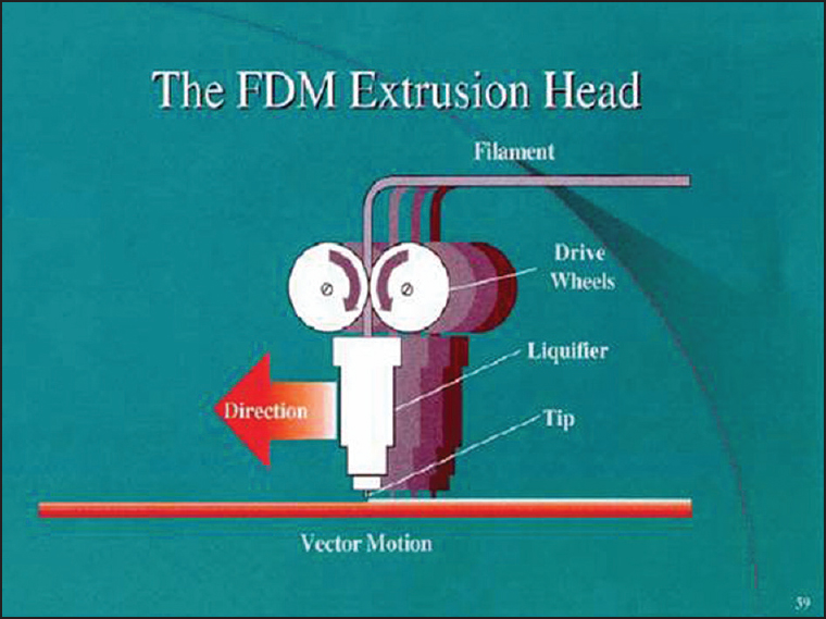
Fused deposition modeling
This is the second most common method after stereolithography. In this technique, the filaments of heated thermoplastic are extruded from a tip that moves in the X-Y plane. Extrusion head deposits thin bead of materials on to build a platform which is maintained at low temperature. Similarly, the layer by layer deposition and hardening takes place to form the object [Figure 3]. The fabrication process involves the use of polycarbonates, investment casting wax, and polyphenylsulfone materials. Fused deposition modeling is the quickest and cheapest method of RP. Prototypes of different colors are possible to make. It is an easy and convenient building process involving less wastage of material with no exposure to toxic chemical materials.
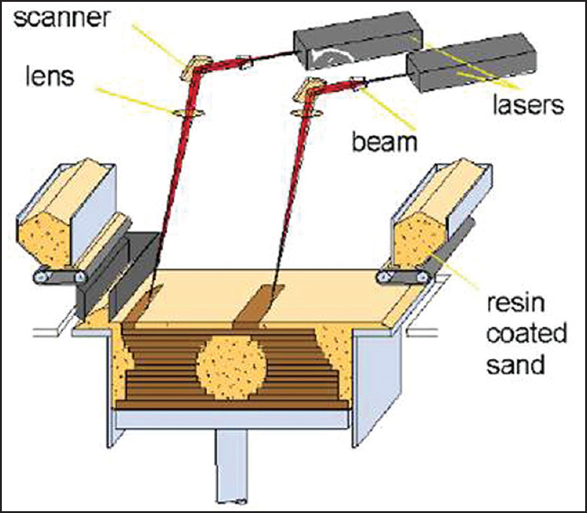
Selective laser sintering
This technique uses a laser beam to selectively fuse powdered materials such as nylon, elastomer, and metal into solid objects [Figure 4]. It is fabrication involves the use of nylon composite, investment casting wax, metallic, ceramic, and thermoplastic composite. This novel technique has the potential to produce the toughest parts with a large range of materials. It is processed in short time and produces a minimal thermal distortion.
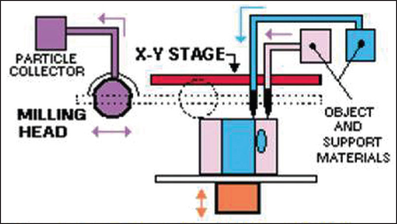
Inkjet printing
Liquid materials such as liquid photopolymer resin are filled into the jetting heads which squirt tiny droplets of the material as they move in X-Y plane into the desired pattern to form the layer of the object [Figure 5]. Advantages of inkjet printing are a fine resolution, accurate surface finish, and minimal material consumption.
Prototype models have numerous uses. They make excellent visual aids for communicating ideas with co-workers or patients. In addition, a prototype has the advantages such as rapid fabrication with minimal time involved and easy handling. Better visualization is possible with repeated verification, and the prototype design can be reused. Its main drawback being cost and even though it is a digital process, clinical judgment still remains vital.
A comparison of different RP techniques has been outlined in [Table 1].
| Application in Orthodontics | | |
Diagnosis and Treatment Planning
Treating an impacted maxillary canine requires identifying its exact position. Faber et al., [14] used RP model as a tool for diagnosis and treatment planning of an impacted maxillary canine. CT slice images were overlapped one on other in 0.5 mm layers. CT files were imported into CT image processing software (Vworks 5.0, Cybermed, Seoul, Korea) and then opened in a prototyping software (Objet Studio, Objet Geometries) and sent to a RP machine (Eden 330 PolyJet, Objet Geometries), where the models were built by overlaying the 0.016-mm layers of acrylic resin polymerized with UV light curing. RP model showed the exact anatomical relationship between the impacted tooth and the other teeth, it served as an aid in intraoperative navigation during surgery to expose the tooth. The model was used to communicate with the patient, his parents and was also used for the fabrication of metal attachment for the canine traction.
Pessa [15] demonstrated the potential role of a high-resolution stereolithography for the study of facial aging. Stereolithography has a role in the preoperative planning of complex dentofacial anomalies. CT scans were collected from younger (mean 20.2 years) and older (mean 58.8 years) individuals (n = 20). An exact replica of the facial skeleton was made for each subject by the process of laser polymerization. The angles of the maxillary wall and piriform aperture as defined by specific points were measured relative to sella-nasion. Height, width, and depth changes were also evaluated. Findings show that angular changes occurred with age. The mean angle of the maxilla relative to sella-nasion decreased from 69° to 56.8° with age. The mean angle of the piriform likewise decreased from 65.1° to 55.7°. Angular change with age suggests that differential growth may continue throughout life. This work highlights the potential role of 3D modeling for future research in the field of facial aging.
Fabrication of Orthodontic Removable Appliances and Impression Trays
Invisalign has gained publicity as the latest high-tech methodology in orthodontic treatment. RP manufacturing of invisalign is time saving with high accuracy. Lee et al., [16] used a set of polyvinyl chloride impressions and sent them to OrthoCAD to generate a fully manipulatable computerized model in STL file format. After completing the 3D image model, the same impression was sent to Align Technology for fabrication of the aligners. The current art of splint making essentially guarantees that the same splint will never be made twice for the same patient. Digitally based manufacturing provides consistency, fine quantitative control, and speed over manual methods. RP provides the direct digital fabrication of plastic and metal parts. [17] Unlike the previous attempts that used an expensive laser scanner for digitization of the patient's dental tissues, the simplicity of this technique is derived from the routine use of cone-beam CT (CBCT) data at a reasonable cost. [18]
CAD and computer-aided manufacturing (CAM) techniques are used in the production of removal orthodontic appliances. A new method of incorporating wire into a single build was developed by Al Mortadi et al. [19] A scanner was used to capture the 3D images of Class II Division 1 dental models that were translated onto a two-dimensional computer screen. The next stage was to export the Andresen design to an AM machine as an STL file ready for fabrication in WaterShed XC 11122 (dsm somos; DSM Headquarters, Elgin, IL, USA). A stereolithography apparatus machine (SLA 250-50; 3D Systems) was chosen for fabrication, since it enables build to be paused and prefabricated pieces to be inserted and built around.
Ciuffolo et al., [20] used RP as a new method of preparing trays for indirect bracket bonding. First, a silicone impression was taken, and the casts produced from these impressions were used to prepare the initial model of malocclusion. Noncontact scanning of the initial model was performed with a high-resolution optical 3D scanner (Structura s.r.l., Ancona, Italy). Results were a surface consisting of many thousands of minute triangles STL surfaces that can be turned, observed, and processed on a computer with dedicated software (CADental, Structura s.r.l.) When brackets have been properly positioned virtually, the fabrication of the RP trays was begun. These custom-made impression trays for indirect bonding have the advantage of time savings and accurate bracket placement.
Orthognathic Surgery
In orthognathic surgery, traditional tools for diagnosis and planning surgical treatment is the cephalogram, dental study cast, and facial photos. However, these have limitations when analyzing the spatial relationships of bony structures accurately, especially when there is a facial asymmetry. Surgeons usually rely on subjective visual estimation and personal experience. Use of a 3D RP model in such cases helps the surgeon to plan and perform surgical procedures to achieve better operative results. It provides an easy way to measure discrepancies due to asymmetry on the model directly, and an opportunity to study the bony structures of the patient and to manipulate them as required before the actual surgery. [2] Surgical splints have also been produced using stereolithography as part of the computer-assisted orthognathic surgery. [21],[22]
Seres et al., [23] presented a case of a severe right-sided hemimandibular elongation. Following presurgical orthodontics, high-resolution CT scan was performed. CT images available in Digital Imaging and Communication in Medicine (DICOM) data were directly transferred to a personal computer. An in-house developed 3D planning software (JMed software, TraumArt Ltd., University of Szeged, Hungary) was used to reformat DICOM stack images into a 3D structure and to perform virtual preoperative surgical planning. Virtual Le Fort-I osteotomy was performed, and the symmetry of the maxilla was corrected with the help of this 3D planning software. A virtual intermediate surgical wafer was designed and produced with 3D RP technology. The mandible was rotated into the correct position following virtual bilateral sagittal split osteotomy to visualize the movements of the osteotomized mandibular segments. The two-jaw procedure was performed according to the virtual plan. The facial symmetry was improved significantly, and stable occlusion was achieved. This complex case shows the advantages of computer-aided surgical planning and 3D RP for the correction of facial asymmetries.
Fabrication of Surgical Template for Implant Placement
Kim et al., [24] fabricated a surgical template for the mini-implant using RP. Positioning of mini-implants on the posterior maxilla was determined by viewing the CBCT images. Data from the CT image are transformed by software for interactive segmentation of the images (Humobot, Seoul, Korea) into a format compatible with a SLA (SLA5000, 3D Systems, Rock Hill, SC, USA). This apparatus uses different laser intensities for segmentation of the tooth and the alveolus in the resin model. Surgical template for the proper positioning of orthodontic mini-implants were fabricated in this way on the replicas of the models; the surgical guides were used for precise placement of the mini-implant. Color 3D RP was used to differentiate teeth, alveolus, and maxillary sinus wall. This surgical guide was placed on the clinical site; it allowed precise pilot drilling and accurate placement of the mini-implant.
Lingual Orthodontics
RP is also used to produce customized lingual brackets for subsequent investment. [25] Lingual appliances need demand for maximum individuality which is met by using CAD/CAM technology. Wiechmann et al., [26] started the manufacturing process by taking a standard two-phase silicone impression. The casts produced from this impression are used to prepare a customized target setup. Noncontact scanning of the therapeutic setup was performed with a high-resolution optical 3D scanner (GOM, Braunschweig, Germany). The outcome was a compound surface consisting of many thousands of minute triangles (STL surfaces) that can be turned, observed, and processed on a computer with an appropriate design software used high-end RP machines to convert the virtual bracket series into a wax analog and then into a final product made of an exceptionally hard alloy with a high gold content.
Customized base permits clear-cut positioning on the tooth, these brackets can be directly bonded by the orthodontist. Archwire geometry was yielded by the 3D location of the bracket slots, the production method used here permitted any clinical shortcomings to be rectified immediately; appliance was tailored to both the existing malocclusion and the preference of the orthodontist. With the technological advances, a new course has now been taken in the manufacture of a bracket-archwire system. It solved three of the most frequently cited drawbacks of lingual appliances: Difficult bonding and rebonding procedures, more frequent accidental debonding, problematic finishing processes, and patient discomfort.
Wiechmann et al., [27] made use of RP technique for attaching Herbst to a lingual orthodontic (LO) appliance. The LO appliance he used was manufactured with state-of-the-art CAD/CAM software coupled with high-end, RP techniques (iBraces/Incognito, Lingualcare, Dallas, Texas, USA). The interface between the LO appliance and the telescopes consisted of a CAD/CAM technologies. Custom-made labial pivot base were connected to the custom-made bands of the maxillary molars and mandibular canines. The individual CAD depiction of the interface ensures an optimal 3D tube-and-plunger position for the correct and smooth function of the telescope mechanism.
Distraction Osteogenesis
Tongue plays an important role in facial growth, Salles et al., [28] described a case report of a patient with aglossia who had dentofacial deformities that affected the mandible in particular. RP models of the jaws were used as an aid for the fabrication of a distractor to produce osteogenic distraction of the mandibular symphysis.
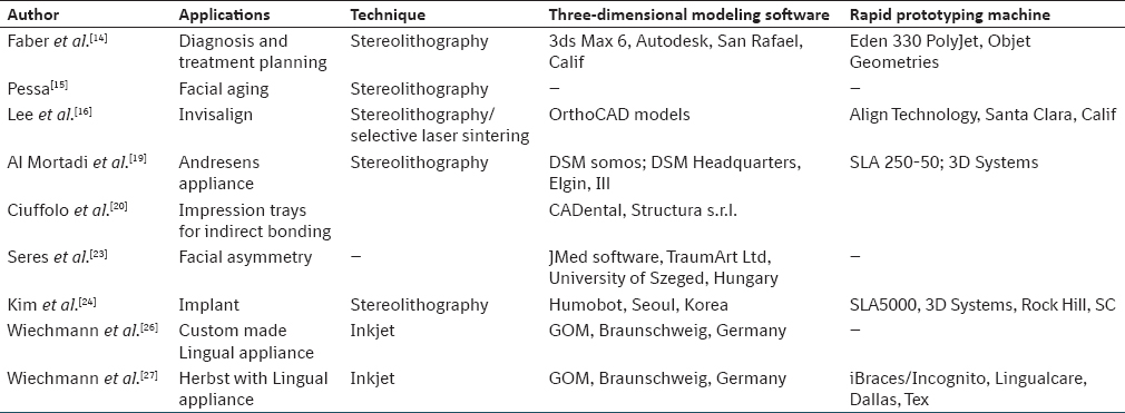
Different RP applications in orthodontics are compared on their mode of modeling software and RP machine used as illustrated in [Table 2].
| Conclusion | | |
Computer numerical control milling machines (CNC machining) involves CAM programming; much time is spent in programming tool paths. Longer periods of machining time are also required. Unlike CNC machining, the entire RP process is efficient without much human input, and models are created quickly. [29] Dental models reconstructed by the tested RP techniques are considered clinically acceptable in terms of accuracy and reproducibility and might be appropriate for selected applications in orthodontics. [30]
The key to applying RP technologies in orthodontics is its inventive nature. This involves using the technologies not only to deliver improvements but also to enable new things which previously might have been impossible or uneconomic. There is a divergence in the applications of RP for an orthodontist and the future looks more promising if he uses it innovatively.
Financial Support and Sponsorship
Nil.
Conflicts of Interest
There are no conflicts of interest.
| References | | |
| 1. | Biglino G, Schievano S, Taylor AT. The use of rapid prototyping in clinical applications. In: Hoque M, editor. Advanced Applications of Rapid Prototyping Technology in Modern Engineering. InTech; 2011. p. 1-21.  |
| 2. | Choi JY, Choi JH, Kim NK, Kim Y, Lee JK, Kim MK, et al. Analysis of errors in medical rapid prototyping models. Int J Oral Maxillofac Surg 2002;31:23-32. |
| 3. | Boboulos MA. CAD-CAM Rapid Prototyping Application and Evaluation. Ventus Publishing ApS; 2010. p. 132-74. |
| 4. | Azari A, Nikzad S. The evolution of rapid prototyping in dentistry: A review. Rapid Prototyp J 2009;15:216-25. |
| 5. | Liu Q, Leu MC, Schmitt SM. Rapid prototyping in dentistry: Technology and application. Int J Adv Manuf Technol 2006;29:317-35. |
| 6. | Weiss LE, Prinz FB. Rapid Prototyping in Europe and Japan. Baltimore, MD: Loyola College of Maryland; 1977. p. 5-20. |
| 7. | Madhav VN, Daule R. Rapid prototyping and its applications in dentistry. J Dent Allied Sci 2013;2:57-61.  |
| 8. | Petzold R, Zeilhofer HF, Kalender WA. Rapid protyping technology in medicine - basics and applications. Comput Med Imaging Graph 1999;23:277-84. |
| 9. | Chan DC, Frazier KB, Tse LA, Rosen DW. Application of rapid prototyping to operative dentistry curriculum. J Dent Educ 2004;68:64-70. |
| 10. | Bidra AS, Taylor TD, Agar JR. Computer-aided technology for fabricating complete dentures: Systematic review of historical background, current status, and future perspectives. J Prosthet Dent 2013;109:361-6. |
| 11. | Hounsfield GN. Computerized transverse axial scanning (tomography). 1. Description of system. Br J Radiol 1973;46:1016-22. |
| 12. | D′Urso PS, Barker TM, Earwaker WJ, Bruce LJ, Atkinson RL, Lanigan MW, et al. Stereolithographic biomodelling in cranio-maxillofacial surgery: A prospective trial. J Craniomaxillofac Surg 1999;27:30-7. |
| 13. | Cuperus AM, Harms MC, Rangel FA, Bronkhorst EM, Schols JG, Breuning KH. Dental models made with an intraoral scanner: A validation study. Am J Orthod Dentofacial Orthop 2012;142:308-13. |
| 14. | Faber J, Berto PM, Quaresma M. Rapid prototyping as a tool for diagnosis and treatment planning for maxillary canine impaction. Am J Orthod Dentofacial Orthop 2006;129:583-9. |
| 15. | Pessa JE. The potential role of stereolithography in the study of facial aging. Am J Orthod Dentofacial Orthop 2001;119:117-20. |
| 16. | Lee HF, Wu B, Ting K. Preliminary studies on invisalign tray fabrication. Am J Orthod Dentofacial Orthop 2002;122:678. |
| 17. | Lauren M, McIntyre F. A new computer-assisted method for design and fabrication of occlusal splints. Am J Orthod Dentofacial Orthop 2008;133(4 Suppl):S130-5. |
| 18. | Nasef AA, El-Beialy AR, Mostafa YA. Virtual techniques for designing and fabricating a retainer. Am J Orthod Dentofacial Orthop 2014;146:394-8. |
| 19. | Al Mortadi N, Eggbeer D, Lewis J, Williams RJ. CAD/CAM/AM applications in the manufacture of dental appliances. Am J Orthod Dentofacial Orthop 2012;142:727-33. |
| 20. | Ciuffolo F, Epifania E, Duranti G, De Luca V, Raviglia D, Rezza S, et al. Rapid prototyping: A new method of preparing trays for indirect bonding. Am J Orthod Dentofacial Orthop 2006;129:75-7. |
| 21. | Yanping L, Shilei Z, Xiaojun C, Chengtao W. A novel method in the design and fabrication of dental splints based on 3D simulation and rapid prototyping technology. Int J Adv Manuf Technol 2006;28:919-22. |
| 22. | Gateno J, Xia J, Teichgraeber JF, Rosen A, Hultgren B, Vadnais T. The precision of computer-generated surgical splints. J Oral Maxillofac Surg 2003;61:814-7. |
| 23. | Seres L, Varga E Jr, Kocsis A, Rasko Z, Bago B, Varga E, et al. Correction of a severe facial asymmetry with computerized planning and with the use of a rapid prototyped surgical template: A case report/technique article. Head Face Med 2014;10:27. |
| 24. | Kim SH, Choi YS, Hwang EH, Chung KR, Kook YA, Nelson G. Surgical positioning of orthodontic mini-implants with guides fabricated on models replicated with cone-beam computed tomography. Am J Orthod Dentofacial Orthop 2007;131(4 Suppl):S82-9. |
| 25. | Mujagic M, Fauquet C, Galletti C, Palot C, Wiechmann D, Mah J. Digital design and manufacturing of the Lingualcare bracket system. J Clin Orthod 2005;39:375-82. |
| 26. | Wiechmann D, Rummel V, Thalheim A, Simon JS, Wiechmann L. Customized brackets and archwires for lingual orthodontic treatment. Am J Orthod Dentofacial Orthop 2003;124:593-9. |
| 27. | Wiechmann D, Schwestka-Polly R, Hohoff A. Herbst appliance in lingual orthodontics. Am J Orthod Dentofacial Orthop 2008;134:439-46. |
| 28. | Salles F, Anchieta M, Costa Bezerra P, Torres ML, Queiroz E, Faber J. Complete and isolated congenital aglossia: Case report and treatment of sequelae using rapid prototyping models. Oral Surg Oral Med Oral Pathol Oral Radiol Endod 2008;105:e41-7. |
| 29. | Martorelli M, Gerbino S, Giudice M, Ausiello P. A comparison between customized clear and removable orthodontic appliances manufactured using RP and CNC techniques. Dent Mater 2013;29:e1-10. |
| 30. | Hazeveld A, Huddleston Slater JJ, Ren Y. Accuracy and reproducibility of dental replica models reconstructed by different rapid prototyping techniques. Am J Orthod Dentofacial Orthop 2014;145:108-15. |
[Figure 1], [Figure 2], [Figure 3], [Figure 4], [Figure 5]
[Table 1], [Table 2]
|


 Search Pubmed for