Comparative stress analysis of delayed and immediate loading of a single implant in an edentulous maxilla model
- Yasuyuki Matsushita, Division of Oral Rehabilitation, Faculty of Dental Science, Kyushu University, 3-1-1 Maidashi, Higashi-ku, Fukuoka 812-8582, Japan. Email: matsushi{at}dent.kyushu-u.ac.jp
Abstract
Stress distribution in peri-implant bone in an edentulous maxilla following delayed and immediate loading implant and the effect of implant length on the maximum stress were evaluated by using two kinds of finite element analyses. A threaded implant was loaded with a 100 N vertical force, either immediately or delayed, and examined by finite element analysis with a simple contact relation or a bonding interaction between the implant and the bone, respectively. Higher stresses were observed in cortical bone around the implant neck following delayed loading and in the trabecular bone around the implant threading in the immediate loading model. The maximum stress in the immediate loading model was dramatically higher than in delayed loading. Increased implant length caused decrease in bone stresses in both loading models. Though the stress level was higher, the decrease in the maximum trabecular bone stress in immediate loading was profound.
Introduction
Immediate loading (IL) implant has come into wide use in oral implant treatments because of the increasing demands of a shortened treatment time. IL implant for the edentulous mandible shows good predictable results in many randomized controlled trials and prospective studies.1⇓–3 However, since clinical evidences regarding IL implant for the edentulous maxilla are not consistent,4,5 it is thought that IL implant for the edentulous maxilla is still not a predictable treatment.
Since the maxillary bone is softer than the mandibular bone, it is difficult to achieve good primary stability at implant placement in maxilla. Furthermore, it is not easy to control occlusal force to IL implant properly, and the occlusal force may cause micromotion of the implant more easily in maxilla than in mandible. These may be the reasons for the inconsistency of clinical evidences for IL implant in the edentulous maxilla. Therefore, it is useful to examine the biomechanics of IL implant to control primary stability and micromotion.
Biomechanics of implant have been analyzed by using finite element analysis (FEA). FEA is a numerical analysis technique which is based on the equation of motion and performs matrix calculations. In conventional FEA, the interface between bone and implant is defined to be perfect bond. Therefore, conventional FEA is not thought to simulate IL condition but delayed loading (DL) condition because the osseointegration is not established in IL condition, whereas osseointegration is established in DL condition. On the other hand, FEA with contact analysis allows transferring compressive force, but no tensile force. Therefore, this contact analysis is thought to be suitable to simulate IL condition. Mellal et al.6 were the first to use contact elements to simulate IL implants in the mandible. Chang et al.7 evaluated micromotion of IL implants in the mandible. Wu et al.8 analyzed stress distribution of IL implant in the mandible with different elastic trabecular bones. However, no contact analysis was done on maxilla. Furthermore, no comparative stress analysis between IL and DL conditions was done. It is important to understand the biomechanical difference between DL and IL by comparing the results of two different FEAs for same clinical conditions such as implant length, number, and location.
The aim of this study was to compare the biomechanical effect of DL and IL for the edentulous maxilla. Hence, the biomechanical effect of implant length on the peri-implant bone was analyzed using conventional and contact FEA.
Materials and methods
Modeling
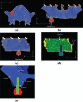
A three-dimensional maxillary model was constructed from a computed tomography (CT) image of a subject with adequate bone mass (Figure 1). The commercially available finite element package, Mechanical Finder 6.2 (Research Center of Computational Mechanics Inc., Tokyo), was used to construct the corresponding numeric situations. Maxillary bone consists of cortical and trabecular bones (Figure 1(d)); the thicknesses of the crestal cortical bone, the lateral wall, and sinus floor wall are shown in Figure 1(e). Our original thread-type implant models (diameter, 4.0 mm; thread pitch, 1.2 mm; intrabony depth, 10, 13, 15, and 17 mm) were made using SOLIDWORKS 2011 computer-assisted design (CAD) software (Dessault Systems, France). A superstructure was also made using the same CAD software.
FEA
All solid models were meshed with tetrahedron elements using ANSYS Academic Meshing Tools (Swanson Analysis Systems (ANSYS), USA). Two “implant–bone” interfaces were used. In the DL implant, the interface of all components was defined as a continuous relation to simulate osseointegration. In contrast, in the IL model, the interface between bone and implant was defined by a contact relation with a friction coefficient of 0.3, which can transmit compressive, but not tensile forces. Furthermore, in the contact condition, frictional forces can be transmitted in proportion to the contact pressure.
Four FEA models assembled with the same maxilla, superstructure, and an implant bearing this superstructure inserted in the second pre-molar region were for the evaluation of DL condition; the implant body at same position was with length of 10, 13, 15, and 17 mm, respectively, and the relation of implant–bone interface was defined to be perfect bond. The countersink around the implant neck was not attached. Only in the 17-mm implant model, the tip of the implant reached the cortical bone in the sinus floor. As the counterparts—four FEA models having same assembling conditions were for the evaluation of IL condition—only the contact relation of the implant–bone interface was different from the DL group.
All materials were homogeneous, isotropic, and linearly elastic. Their Poisson ratios and Young’s moduli are listed in Table 1.9,10
Properties of the various materials featured in finite element analysis model.
The superior border of maxilla model was completely constrained. A vertical force of 100 N was loaded at a central point on the occlusal surface (Figure 1).
Results
Stress distribution in bone
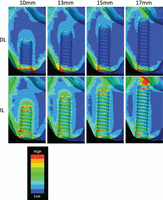
Equivalent stress distributions in the DL model are shown in Figure 2 (upper panels). Markedly higher stresses were observed in the cortical bone around the implant neck, with lower stresses in the trabecular bone around the implant thread. In contrast, high stresses were observed in both cortical and trabecular bones in the IL model (Figure 2, lower panels). Notably, in the bicortical placement of longer implants, high stresses were also observed in the cortical bone of the sinus floor contacting the implant tip.
Comparison of stress distribution in loaded implants of various lengths. Upper panels show implants given time to fully osseointegrate (delayed loading). Lower panels show implants loaded immediately after placement (immediate loading).
Figure 3 shows a comparison of the maximum von Mises equivalent stress (MES) value in cortical (left panel) and trabecular (right panel) bones around DL and IL implants. The maximum MES in cortical bone tended to be greater in the DL model than in the IL model, except for the 17-mm implants. As implant length increased, the maximum MES value in the cortical bone around the implant decreased slightly in both models. The stresses in cortical bone were highest when the 17-mm implants were used.
Maximum equivalent stress values around implants of various lengths placed in cortical bone (left panel) or trabecular bone (right panel). Blue columns denote delayed loading, orange columns are immediately loaded implants.
Maximum stress in the trabecular bone was higher in all cases in the IL model than in the DL model (Figure 3). Stresses in trabecular bone were uniformly low for all implant lengths in the DL model. However, MES values in trabecular bone in the IL model appeared to be length-dependent, decreasing as implant length increased (Figure 3).
MES values in cortical bone decreased slightly with increasing implant length, up to 15 mm. At 17 mm (bicortical fixation), the highest MES was observed in the cortical bone around the implant tip (Figures 2 and 3).
Implant displacement and relative micromotion
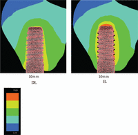
Figure 4 shows the displacement of a 10-mm implant in both the DL and IL models. Predictably, no gap was found at the bone–implant interface in the DL model (Figure 4, left panel), but there was evidence of micromotion between the lower surface of the implant thread and the adjacent bone in the IL model (Figure 4, right panel).
Implant displacement under immediate and delayed loadings. Regions of black shadowing between the implant threads can be seen, which represent micromotion between the implant and bone.
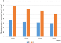
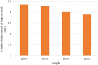
Figure 5 shows the displacement of the implant head at different implant lengths in the DL and IL models. Head displacement was length-dependent, decreasing as implant length increased.
Displacement of the implant head in DL and IL models. Values show average displacement of the implant head under either immediate (orange) or delayed (blue) loadings of various length implants.
DL: delayed loading; IL: immediate loading.
Figure 6 shows the micromotion at interface of implant and bone in IL model.
Discussion
Difference in stress distribution
The conventional concept of osseointegration is that the direct contact relation at the interface of implant and bone provides an anchor mechanism, such that there is no relative motion between implant and bone.11,12 Accordingly, studies have demonstrated high stress concentration at the neck of implants in osseointegrated implant models,13⇓⇓–16 which concurred with our stress distribution results in the DL model. However, we have revealed marked differences in stress distribution in our IL model, which showed that motion existed between the implant and bone (Figure 4). This biomechanical characteristic of the interface resulting in stress distribution throughout the trabecular bone meant that implant shape and length might have a greater influence on stress distribution when immediately loaded. It has been demonstrated that bone resorption frequently occurs in the cortical bone around the implant neck, consistent with our MES stress distribution results in the DL model. However, our results showed that, with IL condition, the implant standing depended on bone tissue around the entire implant body.
Overload of an implant can lead to resorption of the peri-implant bone.16 Anglin et al.17 deduced that on average, the strength of trabecular bone is 10.3 MPa, therefore exceeding this value may lead to bone loss. The mechanical characteristics of IL implants dictated that higher stresses were distributed into the trabecular bone, therefore more appropriate designs of implant shape, length, and placement should be required to decrease the total stress being dissipated through this tissue. For instance, a countersink around the implant neck enables more load to be transferred to the compact bone instead.
Difference in implant displacement (micromotion)
Some movement of an implant under IL is inevitable, and figures of implant “micromotion” during healing in the range of 50–150 µm have been deemed tolerable.18,19 We achieved movements of just 2.5 µm in this study, under loading conditions of a 100-N vertical force. Chang et al.7 also investigated micromotion of 8–15 µm under loading condition of a 300 N vertical load. Both results are considered tolerable. However, trabecular bone was assumed to be homogeneous in this study, but in reality, the implant is supported by discontinuous porous spongy trabeculae. It is believed that the trabeculae were precisely meshed using Voxel method, and it is possible to conduct a much more predictable analysis of the amount of micromotion.
FEM of IL
In recent years, it has been demonstrated that osseointegration is achieved by new bone anchoring into tiny concavo–convex formations within a rough surface and thus completely integrating with a titanium implant. However, this process is quite gradual, and implant longevity is closely linked to how rapidly after implantation it can form bonding contacts with the adjacent bone, a process that will be influenced by stresses being delivered through the implant. The stresses of DL implant are applied well after achieving osseointegration and are thus very different from those delivered to an implant immediately after placement. In this latter situation, the implant has only frictional contact with the bone and no bonding. Because of the different stress patterns of these situations, it becomes necessary to investigate appropriate implant designs for each type of loading, depending on its intended purpose.
FEA is a numerical analysis technique based on the equation of motion of a physical model and performs matrix calculations. Static elastic analysis, a common FEA in dentistry, assumes a continuous state at the interface between the implant and adjacent bone, irrespective of the loading condition. Conversely, conventional FEA specifically models the DL condition. Contact elements of a non-linear structure allow it to transfer compressive, but not tensile, force. Moreover, Coulomb frictional force exists in a shearing direction during transfer of compressive force.20 Mellal et al.6 were the first to use contact elements to simulate IL implants, using them to compare the differences in stress distributions via a screw implant before and after osseointegration in the mandible. Wu et al. analyzed stress distribution via IL implants in two different mandibular bones, one where Young’s modulus of the trabecular bone was set as 1.37 GPa (Type III) and a second with this value set at 0.7 GPa (Type IV). They reported that relaxation of intraosseous stress was best achieved in the Type III bone with short implants, but that longer implants were more effective in the Type IV bone.19 However, their findings in Type III bone differ from our present results, perhaps because their study was modeled in mandibular bone, using a 45°-inclined loading force, and having differing implant thread design to that used here. It is likely that further research will be necessary to provide a definitive proof of the influence of implant length on stress distribution in different types of bone. As shown above, some investigations using contact analysis are found, but there were no reports which compared stress distribution in IL and DL conditions for the edentulous maxilla. Further studies are planned using this maxilla model for the number of implant and location.
Many researchers have concluded that initial stability is a critical factor in the survival of IL implants. To achieve initial stability in practice, the implant is placed in a smaller implantation cavity, causing elastic deformation of the bone and developing initial strains at the bone–implant interface even without any external load. We filtered out the influence of this initial strain in this study, but it will be necessary in future studies to precisely define the effects of applying a load to an implant during the period of initial strain.
Conclusion
We compared the stress distributions in peri-implant bone in an edentulous maxilla. Within the limitations of this study, the following conclusions were formulated:
-
There was a stress distribution difference between the DL and IL models, such that higher stress concentration was observed in cortical bone in the DL model and in the trabecular bone in the IL model.
-
The maximum bone stress was higher in the IL model than in the DL model.
-
Increased implant length may decrease the stress distributed into bone (or at least distribute it more widely) in both the DL and IL models, but this effect is more marked in the IL model.
Acknowledgments
We express our appreciation to Dr Junichi Yamada for his valuable support.
Article Notes
-
Declaration of conflicting interests The authors declare that there is no conflict of interest.
-
Funding This research received no specific grant from any funding agency in the public, commercial, or not-for-profit sectors.
- Received December 27, 2013.
- Accepted April 5, 2014.
- © The Author(s) 2014

