| |


 |
| Year : 2015 | Volume
: 9
| Issue : 4 | Page : 114-120 |
|
|
|
|
|
ORIGINAL ARTICLE Can an extracorporeal glenoid aiming device be used to optimize the position of the glenoid component in total shoulder arthroplasty?
Tom R. G. M. Verstraeten1, Bart Berghs2, Alexander Van Tongel3, David Volders4, Lieven F De Wilde3
1 Department of Radiology, Ghent University Hospital, De Pintelaan 185, B-9000 Gent, Belgium
2 Department of Orthopedic Surgery and Traumatology, AZ Sint-Jan Brugge, Ruddershove 10, B-8000 Brugge, Belgium
3 Department of Orthopedic Surgery and Traumatology, Ghent University Hospital, De Pintelaan 185, B-9000 Gent, Belgium
4 Department of Radiology, AZ Sint-Jan Brugge, Ruddershove 10, B-8000 Brugge, Belgium
Correspondence Address:
Tom R. G. M. Verstraeten
Department of Radiology, Ghent University Hospital, De Pintelaan 185, B-9000 Gent
Belgium
 Source of Support: None, Conflict of Interest: None
DOI: 10.4103/0973-6042.167951
 |
|
|
|
| Date of Web Publication | 22-Oct-2015 |
 Abstract Abstract | | |
Purpose: Successful total shoulder arthroplasty (TSA) requires a correct position of the glenoid component. This study compares the accuracy of the positioning with a new developed glenoid aiming device and virtual three-dimensional computed tomography (3D-CT) scan positioning.
Materials and Methods: On 39 scapulas from cadavers, a K-wire (KDev) was positioned using the glenoid aiming device. It consists of glenoid components connected to the aiming device, which cover 150° of the inferior glenoid circle, has a fixed version and inclination and is available with several different radii. The aiming device is stabilized at the most medial scapular point. The K-wire is drilled from the center of the glenoid component to this most medial point. All scapulas were also scanned with CT and 3D reconstructed. A virtual K-wire (Kct) was positioned in the center of the glenoid and in the scapular plane. Several parameters were compared. Radius of the chosen glenoid component (rDev) and the virtual radius of the glenoid circle (rCT), spinal scapular length with the device (SSLdev) and virtual (SSLct), version and inclination between KDev and Kct, difference between entry point and exit point ("Matsen"-point).
Results: Mean rDev: 14 mm ± 1.7 mm and mean rCT: 13.5 mm ± 1.6 mm. There was no significant difference between SSLdev (110.6 mm ± 7.5 mm) and SSLct (108 mm ± 7.5 mm). The version of KDev and Kct was −2.53° and −2.17° and the inclination 111.29° and 111.66°, respectively. The distance between the "Matsen-point" device and CT was 1.8 mm.
Conclusion: This glenoid aiming device can position the K-wire on the glenoid with great accuracy and can, therefore, be helpful to position the glenoid component in TSA. The level of evidence: II.
Keywords: Glenoid component positioning, glenoid positioning device, three-dimensional computed tomography scan, total shoulder arthroplasty
How to cite this article:
Verstraeten TR, Berghs B, Tongel AV, Volders D, De Wilde LF. Can an extracorporeal glenoid aiming device be used to optimize the position of the glenoid component in total shoulder arthroplasty?. Int J Shoulder Surg 2015;9:114-20 |
How to cite this URL:
Verstraeten TR, Berghs B, Tongel AV, Volders D, De Wilde LF. Can an extracorporeal glenoid aiming device be used to optimize the position of the glenoid component in total shoulder arthroplasty?. Int J Shoulder Surg [serial online] 2015 [cited 2016 Sep 20];9:114-20. Available from: http://www.internationalshoulderjournal.org/text.asp?2015/9/4/114/167951 |
| Introduction | |  |
Accuracy to implant the glenoid component is imperative to prevent loosening of the glenoid component. [1],[2] The aim is to position the glenoid component in such a way that the resulting force vector is in the center of the component. An incorrect positioning of the glenoid can create a rocking horse phenomenon, [3] which can lead to early glenoid component loosening. [4] Recently Hendel et al. demonstrated that, the use of patient-specific instruments (PSI) significantly increases the accuracy of the placement of the glenoid prosthesis. [5] This PSI relies upon the use of a three-dimensional computed tomography (3D CT-scan) reconstruction technology. Today, not all orthopedic surgeons have easy access to this high specific technology. Furthermore, this technology makes the surgical procedure more expensive. The question arises whether an extracorporeal guide can be used as well to reach the same objective.
When developing such an extracorporeal guide, several goals need to be reached.
First of all, the accuracy of the position of the glenoid prosthesis seems to be more important in the transversal plane of the body (anteversion and retroversion) than in the scapular plane of the body (inclination) [6] because of the more limited motion of the scapula in the transversal plane than in the scapular plane of the body. [7] As a bony reference for the evaluation of the version of the glenoid, the medial border of the scapula can be used. [8],[9],[10] The most medial point of the scapula is peroperatively accessible, and its use as guiding bony reference for a clinical guide seemed to be possible.
Next the entry point on the glenoid needs to be defined. Because the glenoid plane with the smallest variability is the inferior circular plane, [8],[9],[10] the center of this circle can be used to define the glenoid center. Even in posterior glenoid erosion, the anterior part of this inferior glenoid circle can be used as a guide to obtaining this inferior circular plane.
Third the aiming device needs to provide guidance to ream the native glenoid plane. This is actually done by the correct placement of a guiding K-wire that is placed perpendicular to the glenoid plane, which is defined by the retroversion × inclination. A previous study, showed that, in a normal population, the average retroversion is 3.4° and the inclination 111.36°. [10] Moreover the standard deviation of the retroversion is, with a confidence interval of 95%, within 3° for the normal population. [8] Because the surgical accuracy is within this order of magnitude, [11] we believe it is surgical appropriate to use a mean retroversion for the clinical guidance of this plane.
The aim of this study was to compare K-wire positioning in the glenoid between an extracorporeal guide and 3D CT-scan reconstruction using a cadaver model.
| Materials and Methods | | |
From the Department of Anatomy Ghent University, 39 scapulas (19 right and 20 left) were selected from 20 cadavers. The scapulas were paired but in one cadaver we could only use the left scapula because of reversed total shoulder prosthesis on the right side. The age of the cadavers (7 male and 27 female) was between 55 and 95 years old. Ethics Committee approval was obtained (EC/2011-378).
Soft tissues (muscle, capsula, ligaments and labrum) were removed from the scapulas and all cartilage from the glenoid.
The glenoid aiming device
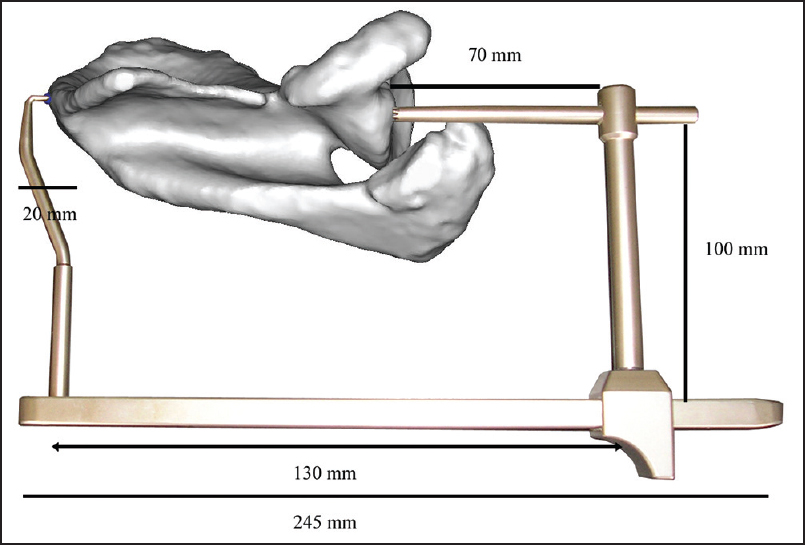
The different components and dimensions of the guide are shown in [Figure 1], [Figure 2], [Figure 3].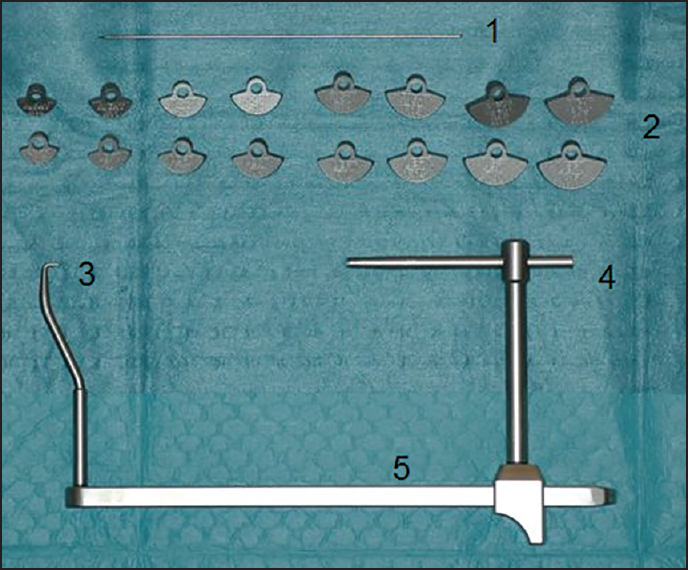 | Figure 1: The different components of the glenoid aiming device. 1 = K-wire of 2 mm diameter. 2 = Different glenoid components from 10 mm to 17 mm, left and right specific. 3 = Pin for fixation of the guide into the most medial point of the scapula. 4 = K-wire guide. 5 = Adjustable mechanism to measure the spinal scapular length (SSLdev). SSLdev: Spinal scapular length with the device
Click here to view |
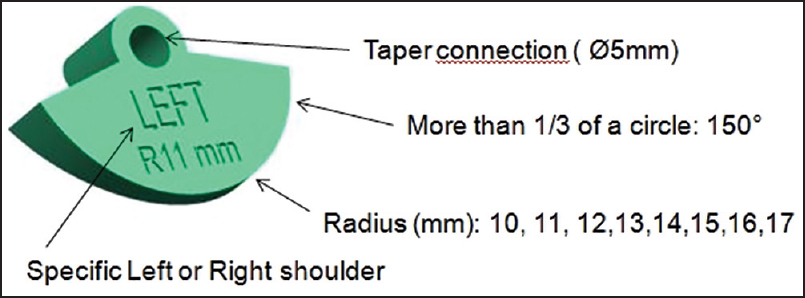 | Figure 3: Detail of a glenoid component. The taper connection is shown for connection with the K-wire guide. The glenoid components are designed to cover 150° of the circle on the inferior glenoid. This is because a more extensively glenoid component touches the more superior part of the glenoid and conflicts with a steady placement on the inferior glenoid. Radius 10-17 mm. Left and right specific
Click here to view |
Eight different glenoid components were made with a radius from 10 mm to 17 mm [Figure 1] and [Figure 3]. All glenoid components have an identical shape with a version of 93.43° and an inclination of 111.36° according to previous 3D CT anatomical studies, [10] and are left and right specific [Figure 4]a, b, and [Figure 5]. The glenoid components are designed in such a manner that they fit the inferior two quadrants of the glenoid when placed on the anterior quadrant of the inferior glenoid [Figure 4]a and b. The glenoid components are designed to cover 150° of the circle on the inferior glenoid [Figure 3]. This is because a more extensively glenoid component touches the more superior part of the glenoid and conflicts with a steady placement on the inferior glenoid. The size is chosen according to the size of the anterior quadrant of the inferior glenoid. These different glenoid components can be connected to the aiming device taper connection [Figure 3]. At the medial side of the scapula, the aiming device can be fixed into the most medial point of the scapula with a pin to obtain a steady measurement. The length of the glenoid aiming device can be adjusted with a sliding mechanism to measure this SSLdev [Figure 1] and [Figure 6]. This is the line between this most medial point of the scapula and the center of the glenoid component. A K-wire of 2 mm in diameter can be placed in the K-wire guide to obtain a steady drilling through the center of the glenoid component and to the most medial point of the scapula [Figure 7]a and b.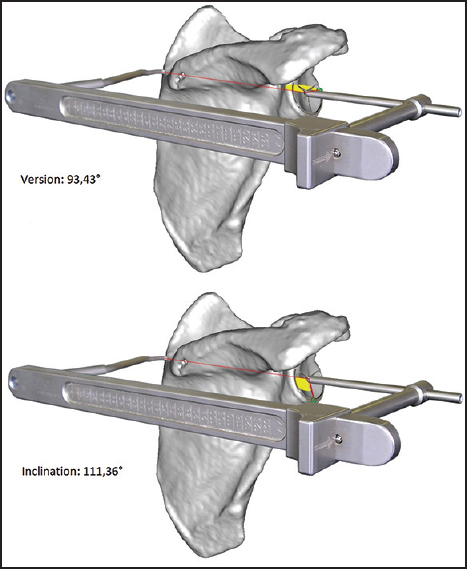 | Figure 4: (a and b) Placement of the glenoid aiming device schematically. The fixed retroversion angle of 93.43° and the fixed inclination angle of 111.36°
Click here to view |
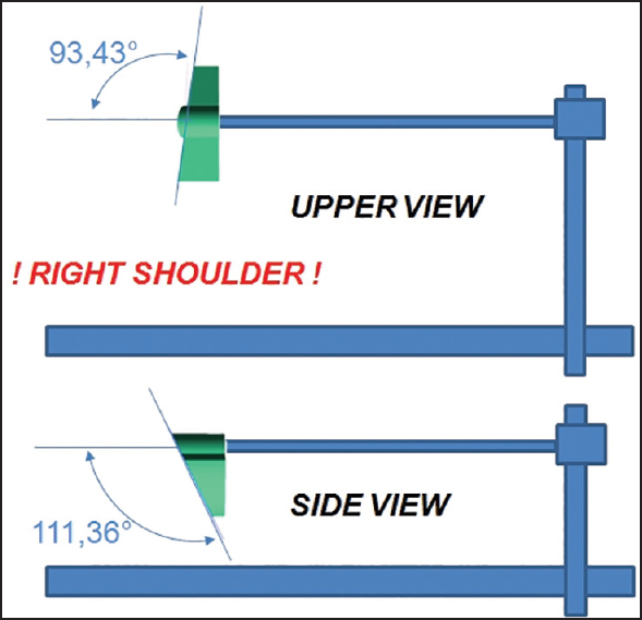 | Figure 5: Upper view and side view schematically of the glenoid aiming device for right shoulder
Click here to view |
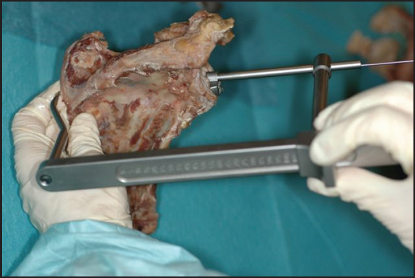 | Figure 6: Placement of the glenoid component onto the glenoid and insertion of the guidance pin at the most medial point of the scapula. K-wire placed in the K-wire guide at the glenoid side. Measurement of the spinal scapular length with the device at the posterior side of the scapula
Click here to view |
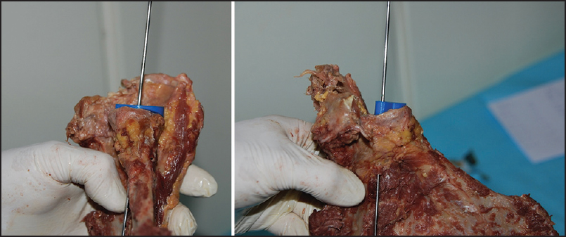 | Figure 7: (a and b) The glenoid component is placed on the glenoid with the K-wire drilled in the center of the glenoid component. The exit point at the anterior glenoid neck
Click here to view |
Surgical technique with the glenoid aiming device
Three surgeons, two experienced surgeons (more than 50 total shoulder prosthesis per year) and one resident, had to choose the radius of the glenoid component (radius 10-17 mm). All three surgeons had to position the glenoid component onto the inferior circular glenoid plane so that the rim of the device shows no overhang to the bone.
Next the glenoid aiming device was mounted on the medial side of the scapula.
With the glenoid aiming device, the spinal scapular length was measured (SSLdev). All scapulae were measured two times for SSLdev with the glenoid aiming device, and intraclass correlation coefficients were used to describe the inter- and intra-observer variability.
Virtual measurements on the three-dimensional computed tomography images
The scapulas were scanned with CT-scan (the specifications of the CT-scanner were General Electric 64 slice Discovery HD, 120kv, 200-300 mAS, matrix 512 × 512, FOV 20).
The DICOM CT images were imported into medical imaging software (Materialise n.v. Haasrode, Belgium: Mimics ® 14.0 for Intel X86 Platform V14.0.0.90 1992-2010) and 3D images of the scapula were created. For determination of bony reference points and measurement purposes, the scapula could be digitally and virtually manipulated. [12],[13]
All scapulas were classified according to Samilson, [14] and all were of type one with osteophytes <3 mm at the inferior glenoid.
At the rim of the inferior glenoid quadrants, we measured the best fitting circle. [8]
The center (Gc) and the radius (rCT) of the inferior glenoid circle were defined. The most medial point of the spina scapula was called MedScap [Figure 8]. The line between MedScap and Gc was the virtual K-wire (Kct) [Figure 9] and [Figure 10] and the distance between MedScap and Gc was defined as the spinal scapular length (SSLct) [Figure 8]. The exit point of the anterior glenoid neck was the "Matsen point ct."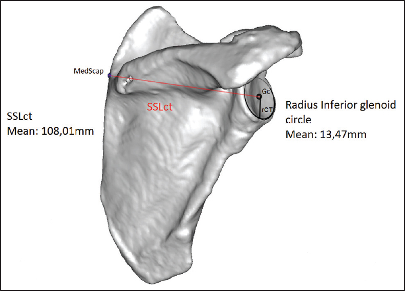 | Figure 8: At the rim of the inferior glenoid quadrants we measured the best fitting circle. The center of the inferior glenoid circle was called Gc. The most medial point of the spina scapula was called MedScap. The line between MedScap and Gc was called the spinal scapular length (SSLct). The SSLct and the radius of the inferior glenoid circle were measured
Click here to view |
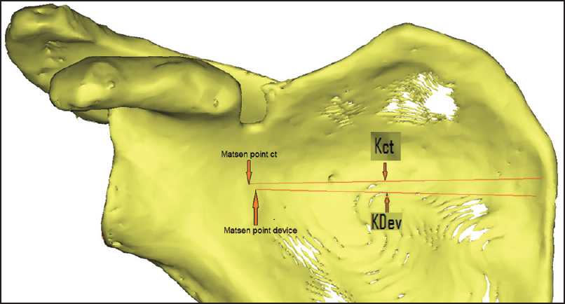 | Figure 9: The point where Kct exits the anterior glenoid neck was called the Matsen point ct. The point where KDev exits the anterior neck was called the Matsen point device. The distance between the Matsen point ct and the Matsen point device was measured
Click here to view |
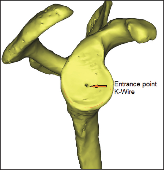 | Figure 10: The entrance point of the K-wire in the center of the glenoid component
Click here to view |
Next the version and the inclination of the KCT was measured with the help of a previous described reference system. [9] For the version, a negative value means a more posteriorly orientated line. For the inclination, a greater value means a more superiorly orientated line.
Measurements on the three-dimensional computed tomography images of the drilled scapulae with the device
Next the entry point on the glenoid and the insertion point of the guide at the medial scapula [Figure 11] were connected. This line was the line of the drilled K-wire (KDev) [Figure 9] and [Figure 10].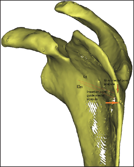 | Figure 11: View of the medial side of the scapula with the insertion point of the glenoid aiming device. In this case, the most medial point of the scapula is slightly higher. The lines Kct (virtual kirschner pinning) and KDev (kirschner pinning with the device)
Click here to view |
As during the virtual measurements on the 3D CT images, the version and inclination of the KDev were measured with the help of a previous described reference system. [9] Next the distance between the "Matsen point ct" and the "Matsen point device" was measured.
Statistical analysis
IBM SPSS statistics 21 (SPSS Inc., Chicago, IL, USA) was used for statistical analysis. The inter- and intra-observer variability for the SSLdev was calculated using the intra-class correlation coefficient. All patients were measured twice independently by two surgeons. A two-way random model with the absolute agreement was used. Paired t-tests were used to compare the measurements between the aiming device and the 3D CT reconstruction images. A linear regression analysis was used to calculate the correlation between the spinal scapular length (SSLdev) measured with the aiming device and the used glenoid component radius.
| Results | | |
Inter- and intra-observer variability
The inter- and intra-observer variability was 0.99 with a 95% confidence interval of (0.979; 0.995) and 0.989 with a 95% confidence interval of (0.979; 0.994) for the measurements of the SSL with the aiming device (SSLdev).
Descriptive statistics
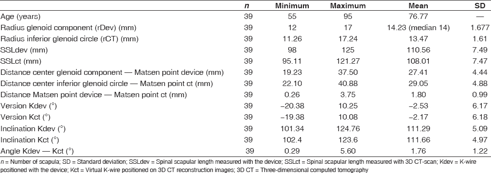
The mean radius of the glenoid components are used with the device was 14.2 mm (median 14 mm) with a standard deviation of 1.7 mm; and the mean radius of the inferior glenoid circle measured with CT-scan was 13.5 mm with a standard deviation of 1.6 mm. The mean SSLdev was 110.6 mm with a standard deviation of 7.5 mm; and the mean SSLct was 108.01 mm with a standard deviation of 7.5 mm.
The mean version of SSLdev and SSLct was −2.53° and −2.17°, respectively. The mean inclination of SSLdev and SSLct was 111.29° and 111.66°, respectively [Table 1].
Comparison results in glenoid aiming device and computed tomography scan measurements
The radius of the glenoid component was measured higher than the radius of the inferior glenoid circle with a 95% confidence interval of (0.59 mm; 0.94 mm). The SSLdev was measured higher than SSLct with a 95% confidence interval of (1.74 mm; 3.37 mm).
The measurement of the version of the device was measured higher with a 95% confidence interval of (0.02°; 0.70°) and the inclination of the device was measured lower with a 95% confidence interval of (−0.24; 1.00).
Matsen point
Between the MCT and MDev, a mean distance of 1.8 mm (±1 mm) was calculated.
Correlations
When evaluating the correlation between SSLdev and rDev, we found a correlation coefficient of 0.75.
| Discussion | | |
Recent literature suggests that the exact 3D guided positioning of a K-wire at the glenoid plane improves the accuracy and the surgical placement of the glenoid component in total shoulder arthroplasty (TSA). [5],[15] This study evaluates the use of a glenoid aiming device to improve the accuracy of the placement of the K-wire to be used in TSA.
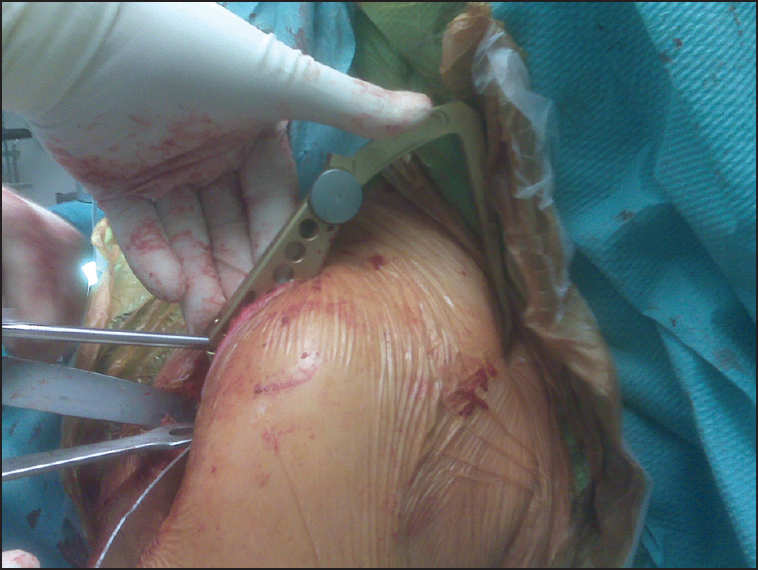
To the best of our knowledge, this study is the first study to describe an extracorporeal guide to placing a K-wire at the glenoid. This guide uses the most medial point of the scapula as point of reference. The use of this medial scapular point introduces a new surgical technique as well for sterile draping as for the surgical approach [Figure 12]. This study did not evaluate those surgeon-related factors yet because first the accuracy and the reproducibility of the surgical technical placement of the K-wire need to be determined.
The clinical inter- and intra-observer variability is excellent, [16] respectively 0.99 and 0.989 for the measurement SSLdev with the glenoid aiming device, and perfect for the choice of the radius of the glenoid component. We are aware that the other parameters, such as the inclination and the version of the virtual Kirshner pin, measured on the 3D CT-scan are more important factors. As described previously, we assume a similar excellent reliability for the 3D CT-scan measurements. [9],[10] This means that the glenoid aiming device can be used with an excellent clinical accuracy by the orthopedic surgeon.
When we compared our results of the glenoid aiming device with the results of the 3D CT-scan, we found that the clinically chosen radius of the glenoid component is slightly bigger than the radius of the inferior glenoid circle measured on 3D CT-scan. A clinical overestimation of the radius of the best fitting inferior glenoid circle, with a confidence interval of 95% between 0.59 mm and 0.94 mm, was calculated. Because the sizes of the glenoid components increase every 1 mm, which is a greater value than the confidence interval, we believe that this is clinically an acceptable result.
When we compare the SSLdev with SSLct, we had a similar finding where the SSLdev is longer than the SSLct. This overestimation of the length varies between 1.74 mm and 3.37 mm with 95% of certainty. To evaluate the clinical consequences of this overestimation, we refer to the relationship between the radius of the inferior glenoid circle and the spinal scapula length. [10] For every increase of a bigger glenoid component, which is an increase of the radius with 1 mm, the SSL increases with approximately 8 mm (equation "radius inferior glenoid = 0.121 SSL -0.232"), which seems clinical acceptable because the confidence interval is less (1.74 mm; 3.37 mm).
We explain this clinical overestimation for both parameters (radius glenoid component and SSLdev) because the surgical glenoid preparation to remove the soft tissue and/or cartilage was slightly imperfect contrasting with the CT-scan measurements, which were pure cortical bony measurements.
When we compare the difference in version and inclination of both lines (SSLdev and SSLct), we found that the SSLdev is more posteriorly (−2.53° instead of −2.17°) and more inferiorly (111.29° instead of 111.66°) orientated compared with SSLct. These measurements of version and inclination have a 95% confidence interval of (0.02; 0.70) and (−0.24; 1.00), respectively which is in the range of the surgical accuracy.
This study also obtained the same correlation between SSLdev and the radius of the glenoid component to previous 3D CT-scan reconstruction results. [10] We confirm that this correlation can help to reconstruct perioperative this native glenoid in cases of posterior erosion of the glenoid such as B2 and C glenoids according to Walch et al. [17]
The introduction and the drilling of the 2 mm diameter K-wire was considered to be very reliable. This is reflected on the one hand by the point of entry on the glenoid side made by the K-wire and the projection of the 3D CT-scan reconstruction center of the inferior glenoid circle. On the other hand the minimal difference (1.8 mm) between the Matsen point device and the Matsen point ct, both measured on the 3D CT-scan reconstruction images, reflects the accurate drilling of the K-wire. This distance is comparable with a previous study done on the location of the glenoid centering line at the anterior glenoid neck. [18] Although the variability can partially explain this difference in selecting the most medial point of the scapula, we believe that this difference can also be partially explained because we used a fixed angulation (inclination and version) of the glenoid device. As mentioned above, because the standard deviation of the retroversion between the scapular plane and the inferior circular glenoid plane is within some degrees (3.35) for the normal population, with a confidence interval of 95%, [8] and because the surgical accuracy is within the same order of magnitude. [11] We decided to use a mean retroversion for this guide instead of a patient-specific guidance. In case of bone erosion, the use of this mean and fixed retroversion can help to predict the native glenoid plane even in the absence of measurements of the contralateral shoulder like in bilateral posterior eroded glenoids. [19],[20]
We are aware of some weaknesses of this study as the limited number of the scapula. Furthermore, the fact that we used 38 paired scapula out of the 39. Nevertheless, we believe that the results of this study are of clinical use because it was our goal was to evaluate the applicability of a new surgical device.
| Conclusion | | |
This study demonstrates that the use of an extracorporeal glenoid aiming device can be applied by the surgeon to position the glenoid guiding K-wire in an accurate way. This can be useful to help the orthopedic surgeon to improve the accuracy of the reconstruction of the native glenoid plane. Although surgeons can be suspicious to use an additional surgical incision with inherent learning curve, we believe that the benefits to using this glenoid guide are worthwhile to consider its use.
Financial support and sponsorship
Nil.
Conflicts of interest
There are no conflicts of interest.
| References | | |
| 1. | Bohsali KI, Wirth MA, Rockwood CA Jr. Complications of total shoulder arthroplasty. J Bone Joint Surg Am 2006;88:2279-92.  |
| 2. | Hasan SS, Leith JM, Campbell B, Kapil R, Smith KL, Matsen FA 3 rd . Characteristics of unsatisfactory shoulder arthroplasties. J Shoulder Elbow Surg 2002;11:431-41. |
| 3. | Gunther SB, Lynch TL, O′Farrell D, Calyore C, Rodenhouse A. Finite element analysis and physiologic testing of a novel, inset glenoid fixation technique. J Shoulder Elbow Surg 2012;21:795-803. |
| 4. | Nyffeler RW, Sheikh R, Atkinson TS, Jacob HA, Favre P, Gerber C. Effects of glenoid component version on humeral head displacement and joint reaction forces: An experimental study. J Shoulder Elbow Surg 2006;15:625-9. |
| 5. | Hendel MD, Bryan JA, Barsoum WK, Rodriguez EJ, Brems JJ, Evans PJ, et al. Comparison of patient-specific instruments with standard surgical instruments in determining glenoid component position: A randomized prospective clinical trial. J Bone Joint Surg Am 2012;94:2167-75. |
| 6. | Mansat P, Briot J, Mansat M, Swider P. Evaluation of the glenoid implant survival using a biomechanical finite element analysis: Influence of the implant design, bone properties, and loading location. J Shoulder Elbow Surg 2007;16 3 Suppl:S79-83. |
| 7. | Ludewig PM, Phadke V, Braman JP, Hassett DR, Cieminski CJ, LaPrade RF. Motion of the shoulder complex during multiplanar humeral elevation. J Bone Joint Surg Am 2009;91:378-89. |
| 8. | De Wilde LF, Verstraeten T, Speeckaert W, Karelse A. Reliability of the glenoid plane. J Shoulder Elbow Surg 2010; 19:414-22. |
| 9. | Verstraeten TR, Deschepper E, Jacxsens M, Walravens S, De Coninck B, Pouliart N, et al. Determination of a reference system for the three-dimensional study of the glenohumeral relationship. Skeletal Radiol 2013;42:1061-71. |
| 10. | Verstraeten TR, Deschepper E, Jacxsens M, Walravens S, De Coninck B, De Wilde LF. Operative guidelines for the reconstruction of the native glenoid plane: An anatomic three-dimensional computed tomography-scan reconstruction study. J Shoulder Elbow Surg 2012;21:1565-72. |
| 11. | Cheng T, Zhao S, Peng X, Zhang X. Does computer-assisted surgery improve postoperative leg alignment and implant positioning following total knee arthroplasty? A meta-analysis of randomized controlled trials? Knee Surg Sports Traumatol Arthrosc 2012;20:1307-22. |
| 12. | Budge MD, Lewis GS, Schaefer E, Coquia S, Flemming DJ, Armstrong AD. Comparison of standard two-dimensional and three-dimensional corrected glenoid version measurements. J Shoulder Elbow Surg 2011;20:577-83. |
| 13. | Lewis GS, Bryce CD, Davison AC, Hollenbeak CS, Piazza SJ, Armstrong AD. Location of the optimized centerline of the glenoid vault: A comparison of two operative techniques with use of three-dimensional computer modeling. J Bone Joint Surg Am 2010;92:1188-94. |
| 14. | Samilson RL, Prieto V. Dislocation arthropathy of the shoulder. J Bone Joint Surg Am. 1983;456-460. |
| 15. | Nguyen D, Ferreira LM, Brownhill JR, King GJ, Drosdowech DS, Faber KJ, et al. Improved accuracy of computer assisted glenoid implantation in total shoulder arthroplasty: An in-vitro randomized controlled trial. J Shoulder Elbow Surg 2009;18:907-14. |
| 16. | Fleiss JL. Analysis of data from multiclinic trials. Control Clin Trials 1986;7:267-75. [ PUBMED] |
| 17. | Walch G, Badet R, Boulahia A, Khoury A. Morphologic study of the glenoid in primary glenohumeral osteoarthritis. J Arthroplasty 1999;14:756-60. |
| 18. | Meyer NJ, Pennington WT, Ziegler DW. The glenoid center point: A magnetic resonance imaging study of normal scapular anatomy. Am J Orthop (Belle Mead NJ) 2007; 36: 200-2. |
| 19. | Friedman RJ, Hawthorne KB, Genez BM. The use of computerized tomography in the measurement of glenoid version. J Bone Joint Surg Am 1992;74:1032-7. |
| 20. | Ganapathi A, McCarron JA, Chen X, Iannotti JP. Predicting normal glenoid version from the pathologic scapula: A comparison of 4 methods in 2- and 3-dimensional models. J Shoulder Elbow Surg 2011;20:234-44. |
[Figure 1], [Figure 2], [Figure 3], [Figure 4], [Figure 5], [Figure 6], [Figure 7], [Figure 8], [Figure 9], [Figure 10], [Figure 11], [Figure 12]
[Table 1]
|