|
 
 |
| ORIGINAL ARTICLE |
|
| Year : 2014 | Volume
: 2
| Issue : 2 | Page : 74-78 |
|
X-ray diffraction of orthodontic archwires for evaluation and comparison of surface deposits: An in vitro study
Avinash Kumar, Prasad Konda
Department of Orthodontics and Dentofacial Orthopedics, Al-Badar Dental College and Hospital, Gulbarga, Karnataka, India
| Date of Web Publication | 22-Apr-2014 |
Correspondence Address:
Avinash Kumar
Department of Orthodontics and Dentofacial Orthopedics, Al-Badar Dental College and Hospital, Gulbarga - 585 102, Karnataka
India
 Source of Support: None, Conflict of Interest: None  | Check |
DOI: 10.4103/2321-3825.131117

Objectives: To evaluate and compare the degree of surface deposits on the archwires with X-ray diffraction (XRD) technique after a period of 6 and 12 weeks of incubation in artificial saliva. Materials and Methods: The three sample archwires: 1. Stainless steel (Truforce), 2. Beta titanium (Betaforce), and 3. Nickel Titanium (Truflex); each with the dimension of 0.017 Χ 0.025 inch and 50 mm length, were constructed into simulated orthodontic appliance and immersed in artificial saliva of pH 6.76 in three different Petri dishes and incubated for a period of 6 and 12 weeks at 37C in an incubator. Wire samples were examined by using XRD technique for surface deposits. Student's unpaired t-test was done to compare the lattice spacing of the control wire (SS) with the test wires and for the comparison of surface deposits between 6 and 12 weeks incubation. Results: After 6 weeks of incubation, no significant difference in the mean values of the lattice spacing between control wire and the test wires was found. The lattice spacing values amongst these test archwires was also found to be insignificant. The test wires showed similar results even after 12 weeks of incubation. Conclusion: XRD analysis showed deposits on these three test archwires after 6 and 12 weeks of incubation which were insignificant. Keywords: Archwires, surface deposits, X-ray diffraction
How to cite this article:
Kumar A, Konda P. X-ray diffraction of orthodontic archwires for evaluation and comparison of surface deposits: An in vitro study. J Orthod Res 2014;2:74-8 |
How to cite this URL:
Kumar A, Konda P. X-ray diffraction of orthodontic archwires for evaluation and comparison of surface deposits: An in vitro study. J Orthod Res [serial online] 2014 [cited 2018 Mar 4];2:74-8. Available from: http://www.jorthodr.org/text.asp?2014/2/2/74/131117 |
| Introduction | |  |
Orthodontic archwires are liable to surface deposits and corrosion because they are immersed in electrolytic saliva. Factors such as oral temperature, the presence of plaque and some foods and beverages along with systemic and oral health conditions provide a corrosive environment. [1],[2]
Earlier studies have focused on the intraoral aging of NiTi wires and inner archwire of stainless steel (SS) face bows. It was found that the archwire surfaces were coated by proteinaceous biofilm that mask the alloy surface topography, which is dependent on individual's oral environmental conditions and on the intraoral exposure period. The biofilm consists of precipitates of sodium chloride, potassium chloride, and calcium phosphate crystalline on the archwire surfaces. [3],[4]
Potential treatment effects of surface deposits on the archwires are variation in friction and torque expression. Friction might vary because of development of biofilm.
Torque expression might be altered because of inability for complete wire engagement. [5] Shin et al., [6] investigated surface deposits on SS and NiTi archwires by using X-ray diffraction (XRD) method. XRD is a method of material testing, which is surface sensitive in region of interest for layered or surface-treated materials.
The development of unwanted deposits on archwires is inevitable under normal oral conditions. Knowing the susceptibility of archwires to such deposits will help to establish the least susceptible wire and consequently its use to render highest quality of treatment possible.
The present study was conducted in vitro to compare the surface deposits on the SS, beta titanium, and nickel titanium archwires with XRD technique after 6 and 12 weeks of incubation in artificial saliva.
| Materials and Methods | | |
Artificial saliva was prepared with the following composition: 0.4 g NaCl, 0.4 g KCl, 0.8 g CaCl 2 .2H 2 O, 0.01 g NaS.5H 2 O, 1 g CO(NH 2 ) (urea), and 1 l distilled water. The three test archwires: 1. SS (Truforce), 2. beta titanium (Betaforce), and 3. nickel Titanium (Truflex) and control wire (SS) were from Ortho Technology Inc, Boulevard, Tampa, Florida, USA; each with the dimension of 0.017 × 0.025 inch and 50 mm length.
Simulated fixed orthodontic appliances were constructed with band material, brackets, archwires, and ligature wires. Molar band materials (Ortho Technology Inc) of 0.180 × 0.005 inch dimensions were cut into strips of 60 mm each. Standard edgewise brackets of 0.022 × 0.028 inch slot size were welded on these band stripes equidistantly with two welds each, leaving 10 mm of space on both ends and 10 mm distance in between each bracket. Six such samples of five brackets each were prepared.
Test samples were divided into three groups according to the alloy used: Group I: Comprised of SS test archwires; Group II: Comprised of beta titanium test archwires; and Group III: Comprised of nickel titanium archwires. Each group consisted of two samples. All these samples were immersed in artificial saliva of pH 6.76 (pH meter Slope model: 111E) in three different Petri dish More Detailses according to the group and incubated for a period of 6 and 12 weeks at 37°C in an incubator. According to the period of incubation each group is divided into two subgroups. Subgroup A was incubated for a period of 6 weeks. Subgroup B was incubated for a period of 12 weeks.
After the incubation, the wire from sample of each subgroup was sectioned to lengths of 10 mm each and arranged flat on the sample holder in an area of 1 cm 2 on a double side sticking tape, for detection of surface deposits with XRD technique. X-ray diffractometer (Bruker AXS, Germany) with CuKα΄ radiation at 40 kVp and 30 mA was used. Both the divergent and receiving slits were of 1°. The scan range used was between 2 and 7°.
Bragg's law [7] was used in XRD technique: nλ = 2dsinθ
λ = angle of the incident X-ray beam
d = distance between atomic layers in a crystal
θ = wave length of the incident x-ray beam
n = integer.
Bruker software was used for plotting data, locating peaks, calculating d-spacing, and lattice spacing. Comparison of diffraction peaks was done with JCPDS files (Joint Committee on Powder Diffraction System, USA).
Statistical Analyses
Student's unpaired t-test was carried out for the comparison of surface deposits between the control wire and the test wires and for the comparison of surface deposits between 6 and 12 weeks of incubation amongst test wires. Conventional levels of significance were used: P < 0.05, significant; P > 0.05, not significant.
| Results | | |
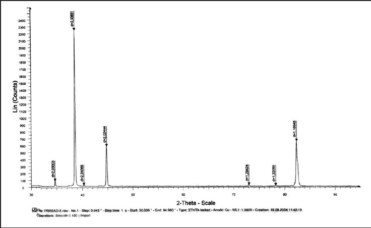
Data of XRD peaks of control wire and three test wires after 6 and 12 weeks of incubation is shown in [Figure 1],[Figure 2],[Figure 3],[Figure 4],[Figure 5],[Figure 5],[Figure 6] and [Figure 7]. Mean and standard deviation for the lattice spacing of control wire and all the three test archwires after 6 and 12 weeks of incubation is calculated [Table 1].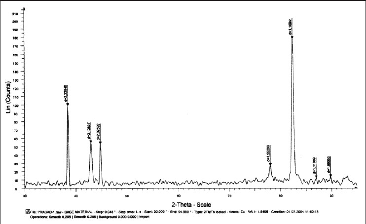 | Figure 1: Graph showing X-ray diffraction peaks of control wire (stainless steel)
Click here to view |
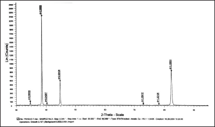
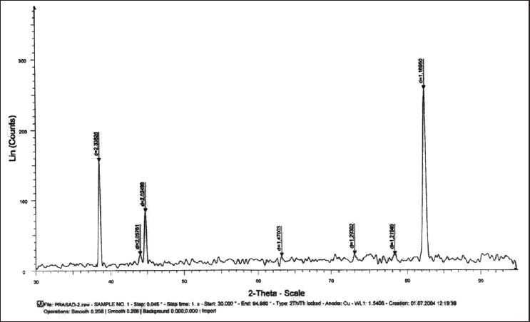 | Figure 2: Graph showing X-ray diffraction peaks of stainless steel test wire after 6 weeks of incubation
Click here to view |
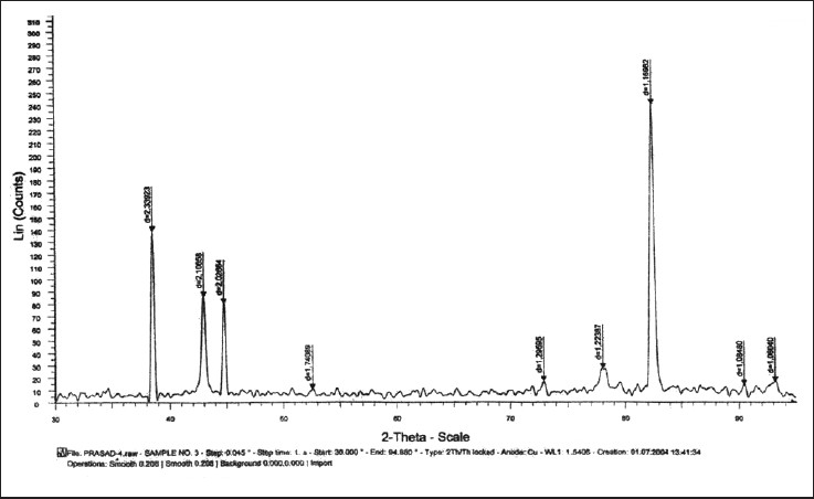 | Figure 3: Graph showing X-ray diffraction peaks of beta titanium test wire after 6 weeks of incubation
Click here to view |
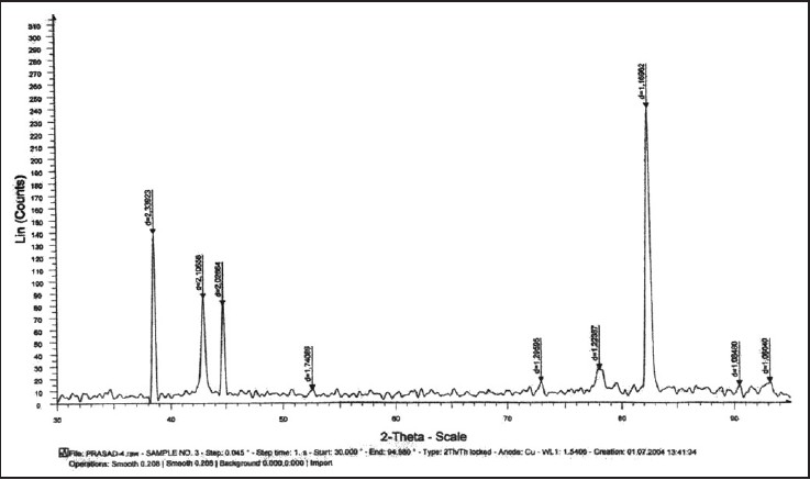 | Figure 4: Graph showing X-ray diffraction peaks of nickel titanium test wire after 6 weeks of incubation
Click here to view |
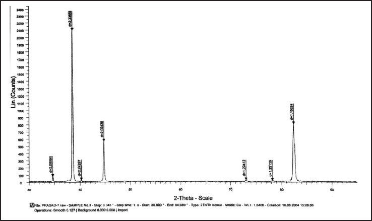
 | Figure 5: Graph showing X-ray diffraction peaks of stainless steel test wire after 12 weeks of incubation
Click here to view |
 | Figure 6: Graph showing X-ray diffraction peaks of beta titanium test wire after 12 weeks of incubation
Click here to view |
 | Figure 7: Graph showing X-ray diffraction peaks of nickel titanium test wire after 12 weeks of incubation
Click here to view |
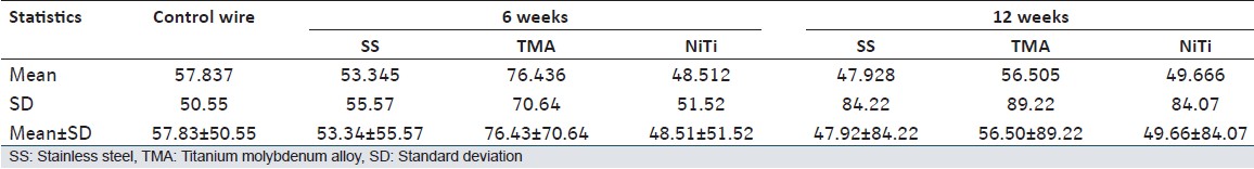 | Table 1: Shows mean, standard deviation, and mean ± SD of the lattice spacing of control wire and all the three wires after 6 and 12 weeks of incubation
Click here to view |
Comparison of Surface Deposits Between Control Wire and three Test Wires
The comparison of surface deposits after 6 weeks of incubation of control wire and three test wires does not show significant difference in the mean values of the lattice spacing. The archwires showed similar results even after 12 weeks of incubation [Table 2].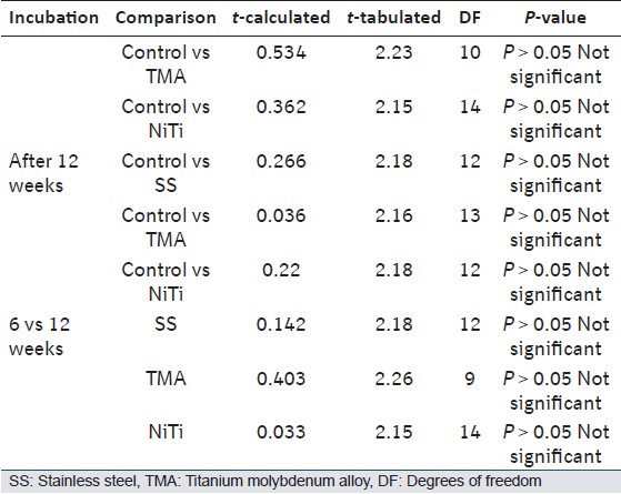 | Table 2: Shows results of Student's unpaired t-test for the lattice spacing comparison between the control and test wires
Click here to view |
Comparison of Surface Deposits Amongst three Test Wires at 6 and 12 Weeks of Incubation
The comparison does not show significant difference in the mean values of the lattice spacing amongst test archwires after 6 weeks of incubation. Even after 12 weeks of incubation the test archwires showed no significant deposits [Table 3].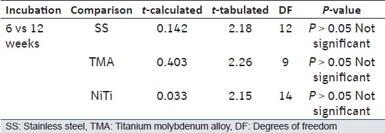 | Table 3: Shows results of Student's unpaired t-test for the lattice spacing comparison between the test wires at 6 and 12 weeks
Click here to view |
| Discussion | | |
XRD is most widely used for the identification of unknown crystalline materials (e.g., minerals and inorganic compounds). Determination of unknown solids is critical to studies in material science. One of the most important uses of XRD is to obtain XRD pattern, measure spacings, obtain integrated intensities, and compare data with known standards in the JCPDS file which are for random orientations. Typical XRD equipment includes: X-ray tube or source; sample holder, goniometer for angle measurement; X-ray detector for intensity measurement; and optics for beam filtering and columniation. The wavelength of rays is similar to the spacing between planes of atoms in materials. As a result, planes of atoms constructively interfere with roentgen rays resulting in diffraction. Bragg's law allows the calculation of interplanar spacing or d-spacing from the angular location of XRD peaks. [7],[8],[9]
In the present study, the XRD is used to compare the lattice spacing between the control wire and the three test wires, which were incubated in artificial saliva for 6 and 12 weeks. After 6 weeks of incubation though deposits were found on the test wires compared to the control wire; they were insignificant. Even after 12 weeks of incubation the wires showed no significant deposits. On comparison between the surface deposits at 6 and 12 weeks of incubation amongst the test wires, the results showed no significant difference. Marques et al., [10] investigated the degree of debris and roughness of SS orthodontic archwires with scanning electron microscope before and after clinical use. When SS rectangular wires were exposed to the intraoral environment for 8 weeks, a significant increase in the degree of debris and surface roughness was observed. This change was correlated to an increase in friction between the wire and bracket during the mechanics of sliding. The variation in the results of our study can be attributed to the in vitro conditions.
Shin et al., [6] conducted an in vitro study to evaluate and identify the surface deposits on SS and NiTi archwires by using XRD method. They observed that, after 12 weeks of immersion the surface deposits found on SS wires were more than that on the NiTi wires. In the present study, no significant difference in the degree of surface deposits on the three test archwires was observed. However, the surface deposits on titanium molybdenum alloy (TMA) were found to be more compared to NiTi, which in turn was more than SS archwire. Hence, SS being the wire with least amount of surface deposits.
Limitations of the Study
The conditions in the oral cavity differ from the in vitro arrangements. An absence of the complex intraoral flora, accumulation of plaque, and its byproducts is the most important difference. Fixed orthodontic appliances in the oral cavity are also exposed to stress and friction due to masticatory function, which may affect the surface deposits on the archwires. [11] Hence, further research is required to address the effect of in vivo aging on surface properties of the archwires.
| Conclusion | | |
Though XRD analysis showed surface deposits on SS, nickel titanium, and beta titanium test archwires after 12 weeks of incubation; however, they were insignificant compared to control wire also there was no significant difference in surface deposits amongst the three test archwires.
| References | | |
| 1. | von Fraunhofer JA. Corrosion of orthodontic devices. Semin Orthod 1997;3:198-205. 
[PUBMED] |
| 2. | Maijer R, Smith DC. Biodegradation of the orthodontic bracket system. Am J Orthod Dentofacial Orthop 1986;90:195-8.
[PUBMED] |
| 3. | Eliades T, Eliades G, Athanasiou AE, Bradley TG. Surface characterization of retrieved NiTi orthodontic archwires. Eur J Orthod 2000;22:317-26.
|
| 4. | Eliades T, Eliades G, Watts DC. Intraoral aging of the inner headgear component: A potential biocompatibility concern? Am J Orthod Dentofacial Orthop 2001;119:300-6.
|
| 5. | Eliades T, Bourauel C. Intraoral aging of orthodontic materials: The picture we miss and its clinical relevance. Am J Orthod Dentofacial Orthop 2005;127:403-12.
|
| 6. | Shin JS, Oh KT, Hwang CJ. In-vitro surface corrosion of stainless steel and NiTi orthodontic appliances. Aust Orthod J 2003;19:13-8.
|
| 7. | Thayer TA, Bagby MD, Moore RN, DeAngelis RJ. X-ray diffraction of arch wires. Am J Orthod Dentofacial Orthop 1995;107:604-12.
|
| 8. | Klug HP, Alexander LE. X-ray diffraction procedures for polycrystalline and amorphous materials. 2 nd ed. New York: Wiley; 1974.
|
| 9. | Moore DM, Reynolds RC Jr. X-Ray diffraction and the identification and analysis of clay minerals. 2 nd ed. New York: Oxford University Press; 1997.
|
| 10. | Marques IS, Arau´jo AM, Gurgel JA, Normando D. Debris, roughness and friction of stainless steel archwires following clinical use. Angle Orthod 2010;80:521-7.
|
| 11. | Eliades T, Athanasiou AE. In vivo aging of orthodontic alloys: Implications for corrosion potential, nickel release, and biocompatibility. Angle Orthod 2002;72:222-37.
|
[Figure 1], [Figure 2], [Figure 3], [Figure 4], [Figure 5], [Figure 6], [Figure 7]
[Table 1], [Table 2], [Table 3]
|


 Search Pubmed for