


Measurement of Orthodontic Bracket Tie Wing Elastic and Plastic Deformation by Arch Wire Torque Expression Utilizing an Optical Image Correlation Technique
- Ryan A. Lacoursiere lacours{at}ualberta.ca1
- David S. Nobes david.nobes{at}ualberta.ca2
- Darren L. N. Homeniuk homeniuk{at}ualberta.ca2
- Jason P. Carey jason.carey{at}ualberta.ca2
- Hisham H. Badawi hbadawi{at}ualberta.ca1,3
- Paul W. Major major{at}ualberta.ca1
- 1Orthodontic Graduate Program, Department of Dentistry, Faculty of Medicine and Dentistry, University of Alberta, Edmonton, AB, Canada, T6G 2N8
- 2Mechanical Engineering, Faculty of Engineering, University of Alberta, Edmonton, AB, Canada, T6G 2G8
- 3Private Practice, Suite 140-12024, Symons Valley Road NW, Calgary, AB, Canada, T3P 0A3
Abstract
Orthodontic lingual root movement (torque) is an important aspect of treatment biomechanics and is typically achieved by torsion of a rectangular wire within the orthodontic bracket slot which introduces a force couple. The magnitude of the force moment achieved by wire torsion may be influenced by deformation of the orthodontic bracket. A device utilizing an optical image correlation technique has been developed to accurately quantify bracket slot dimensional changes during application of wire torsion. Simultaneous torque moment magnitude, degrees of wire twist, and bracket slot dimension data can be gathered. Bracket tie wing elastic deformation when loaded was demonstrated and plastic deformation was also observed with a single rotation of the wire.
1. Introduction
In orthodontics the term torque can be used to refer to the buccal-lingual root inclination of a tooth, rotation of a tooth about the “x-axis” passing through an orthodontic bracket or the force moment needed to generate buccal-lingual root tipping. Torquing force moments are most often obtained during the course of orthodontic treatment through a force couple generated by the torsion of a rectangular archwire in a rectangular bracket slot [1]. Wire twists as high as 50° have been used clinically. Many factors have been found or thought to affect torque expression, namely, torsion magnitude, wire composition, torsional stiffness, wire dimension, wire/bracket slot play, tooth inclination, interbracket width (wire length), and bracket deformability [2–9].
The optimum orthodontic force magnitude has not been well defined [10] but is related to periodontal ligament stress level, projected root surface area, as well as the individuals biologic response. Periodontical ligament compression approximating 200 g/cm2 [11, 12] has been reported as an effective estimate to establish effective orthodontic force systems. While recognizing the limitations of existing research, clinically effective torque moments for lingual root movement of an upper central incisor have been reported as 5–20 Nmm [13, 14]. Accurately measuring and predicting torque expression and understanding the sources of losses are critical to providing predictable orthodontic treatment results. Several studies have measured in vitro torque expression using different devices and techniques looking at wire/bracket play, different brackets, and wire configurations, among other variables showing that torque expression was largely affected by these variables [2–5, 8, 14–21].
Few have investigated the behavior of the bracket using finite element approaches or analytical modeling. The work in [22] Middlcton et al. who investigated the mechanical behavior of fixed orthodontic brackets with emphasis on the bracket base and tooth surface interface is the most recent. Peak stresses were located at the base of the loaded tie wing. No information as to tie wing deformation was discussed.
An area of interest for developing torque expression on the tooth is the potential impact of bracket deformation under loading. Evidence of bracket deformability and flexion has been mostly anecdotal. The early work of Flores et al. [23] and Kapur et al. [24] showed that permanent deformation could occur at elevated stress levels and that titanium brackets had better dimensional stability than stainless steel brackets. Clear evidence of bracket deformation has yet to be shown in literature.
Our group assessed that there was a need for quantitative investigation of the wire/bracket system to highlight the loads imparted onto the bracket and those transmitted to the bracket base and to evaluate the impact of loading on the bracket. It was hypothesized that bracket deformation occurred when torque was applied through the use of a wire, which could be both elastic and permanent. This pilot study investigated these phenomena using a novel imaging system, which was added to an existing single axis torsion device [21], that was custom made for this investigation. A similar approach was used for full-field polymerization shrinkage and depth of cure of dental composites [25]. It was the objective of this study to demonstrate clear evidence of bracket deformation as a result of applied torsional loads.
2. Experiment Outline
Ormco Orthos 0.022 in (0.56 mm) slot stainless steel upper right central incisor brackets with a 15-degree prescription and Ormco 0.019 in × 0.025 in (0.483 mm × 0.635 mm) stainless steel wires (Ormco Corporation, Division of Sybron, Orange, CA) combination was used in the experiment to establish if bracket slot deformation occurred; the bracket and wire were tested once only.
The torque expression jig and torquing procedure described in [21] 2008 was modified. Briefly, the bracket/archwire torsion device has the capability of applying pure torsion to the wire using a force zeroing technique that maintains a perfect vertical and horizontal alignment between the wire and the bracket. A rendered image of the combined systems and components is shown in Figure 1. The in-house developed apparatus consists of a holder to locate a mounting bracket onto which the orthodontic bracket is glued. The archwire, as shown in close-up photograph in Figure 2, is held in a set of split-finger dies that are mechanically locked to each other via a torquing arm. The structure was slightly modified to increase the field of view compared to the work in Badawi et al. 2008 [21]. This arm provides the rotation needed to implement torque in the archwire and hence to the bracket. A worm and worm-wheel gear-box is used to couple the torquing arm to a computer controlled stepper motor (Cool Muscle CM1-C-11L30, Myostat Motion Control Inc., Newmarket, ON, Canada). Custom software was written (LabWindows/CVI, National Instruments, Austin, TX, USA) to control motor rotation as well as simultaneous data acquisition from the load cell (Nano17, ATI Industrial Automation, Apex, NC, USA), inclinometer (T2-7200-1N inclinometer, USDigital, Vancouver, WA, USA) and camera (discussed below). Real-time feedback via on-screen display of loads and images of the bracket allowed adjustment of bracket position and wire rotation to ensure that the archwire was fully engaged with the bracket and that minimum load was transmitted between the wire and bracket. This is defined as the neutral position of the wire in the bracket.
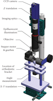
A rendered image of the single axis torque expression rig.
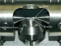
A close-up photograph of the wire held in support dies loading the bracket and load cell.
To investigate the interaction of the archwire with the bracket while under torquing an imaging system was adapted to work in conjunction with the single axis torsion rig. As shown in Figure 1, a high-resolution CCD camera (piA2400-12gm, 2448 × 2050 pixels, 8bit, gray scale, Basler Vision Technologies, Exton, PA, USA) is coupled to a long working distance microscope (Edmund Optics, 55-908 MMS R4, Barrington, NJ, USA). Epi-illumination allows on-axis introduction of light into the region where the archwire engages with the bracket. Magnification is selected to maximize the bracket in the field of view. A typical image captured from the system is shown in Figure 3. Images are taken at every 3 degrees of torsion increment. The imaged region is aligned with the archwire, and above and below the wire, bracket tie wings can be seen. The thin focal plane of the imaging optics renders the bottom of the bracket and holder out of focus. To improve image quality and minimize surface reflectivity, brackets were etched using a microetcher (The Arum group, Spokane, WA, USA) with Ortho Technology TruEtch 50 micron Aluminum oxide item number 12300.
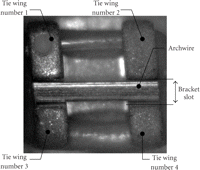
A typical image collect from the image system showing the scale and components of the bracket/archwire system.
To quantify the separation of the tie wings, an image correlation technique was used on the collected images to measure the relative motion of objects in the image between frames. The image was broken into subwindows which was correlated between frames using a mathematical correlation algorithm [26, 27] that compares contrast features within an image. The resultant correlation map, which is the same size as the subwindow, will have a peak maximum that represents the average displacement of the image over that sub-window. This average is represented by a displacement vector from the centre of the subwindow to the correlation peak. The measurement resolution is mainly dependent on the accuracy with which the correlation peak can be detected. This is typically 1/10th of a pixel [26]. For the current setup this equates to a measurement resolution of 0.15 μm. Advanced algorithms that allow for interrogation window off-set, window distortion, and multiple window size adjustment are available. The collected image data were processed using a commercial code (LaVision GmbH DaVis 7.2. Gottingen, Germany; 2007).
To investigate the separation of tie wings, a box region within each individual tie wing was tracked through the data set. These regions are shown in Figure 4 as green boxes with an image of the initial location shown in Figure 4(a). As the bracket is torqued by the archwire, there are both a relative motion between the tie wings as they separate and a bulk motion as the whole bracket moves within the image. This second motion is due to the bracket holder and load cell moving under load. The original position was tracked in subsequent images and the maximum movement which included relative and bulk motion is shown in Figure 4(b). An image of the bracket after the applied torque has been removed is shown in Figure 4(c) with the tracked region shown as yellow boxes. It can be seen here that the pre- and postposition of the tie wings is not the same, indicating that there has been a permanent deformation of the bracket.
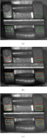
Image of brackets showing the location of tracked regions, (a) the original positions (green box), (b) maximum separation (red box) and (c) final, un-torqued location indicating permanent deformation (yellow box).
All data acquisition and control of the experiment was carried out using the custom software. The total rotation and the number of measurement points for the experiment were predetermined and loaded before experiment execution. At the start of the experiment data were collected from the 6-axis load cell and the inclinometer and an image of the wire/bracket was collected. Upon completion of data collection at a measurement point, the program instructs the stepper motor to move to the next data collection point defined as a set rotation angle. Data were collected in this manner at each measurement point from 0° to a maximum of 51° in steps of 3° of rotation of the archwire. Data were collected both as torque was applied to the bracket and as it was relieved, which led to a total of 36 data points.
3. Results and Discussion
Visual evidence of the interaction of the archwire as it was rotated within the bracket slot is shown in Figures 5(a)–5(r). This figure is a collection of images from every second sample point in the experiment. The amount of applied torque by the archwire in terms of the applied angle is given in individual captions. The images are of the same field of view and scale as the example given in Figure 3 and example tracking in Figure 4. Archwire rotation is evident with the change in reflection as the archwire surface progressively becomes normal to the illumination and camera. The archwire passes through this point both as that angle is increased (Figures 5(c)–5(f)) and decreased (Figures 5(o), 5(p)). Evidence can also be seen in the images of separation of tie wings as torque is applied to the bracket. In Figure 5(a), the archwire fits neatly in the bracket slot and there is a minimum gap between tie wings 1 and 3. Consider the left column of images (Figures 5(a), 5(d), 5(g), 5(j), 5(m), and 5(p)). As the wire is rotated, a gap opens up between the archwire and tie wing 3. This is the largest in Figure 5(j) at the maximum rotation of the archwire and is evidence that there is deformation in the bracket.
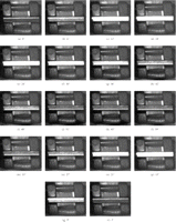
Images of the bracket as it is progressively torqued by the archwire. Noted with each image ((a)–(r)) is the angle applied by the single axis torque rig.
Quantitative measurement of the relative displacement between the tie wings can be made by averaging the displacement vectors within the tracking boxes described in Figure 4. This is calculated for tie wing pairs (1 and 3, 2 and 4) as defined in Figure 3 and displayed in Figure 6 as a function of the applied rotation angle (Figure 6(a)) and sample number (Figure 6(b)). This second figure is included to better indicate the sequence of events as torque is applied and relieved from the bracket. A direct comparison is also made in the same figure of the expressed torque (Tx) and the measured increase in bracket slot width. The plots show that while the torque is being applied, there is a near linear increase in both the expressed torque and the spacing between tie wings. However, on release of the torque loading the expressed torque follows a linear decay while the spacing between tie wings is clearly nonlinear. The expressed torque also levels off earlier (30° on return at sample number 25) while the bracket slot continues to contract (∼17° on return at data sample number 28). This is perhaps due to the complex interaction of the square cross-section archwire, the bracket slot geometry, and bracket prescription. On complete removal of torque that bracket slot width was larger by approximately 20 μm, indicating that the bracket has been permanently deformed after a single expression to 51°, there is also some residual torque which could be the result of the deformation of the bracket tie wings as well as permanent twist in the archwire generate during the expression. The second feature was observed in the archwire postexperiment.
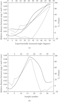
A comparison of the expressed torque (Tx) (dashed line) and relative change in bracket slot width (solid line) as a function of (a) measured angle and (b) collected sample number.
The results of this pilot study demonstrate that bracket deformation is likely a significant factor in loss of torque expression. The amount of bracket deformation will likely vary between bracket designs and metal composition within the brackets. Furthermore ligation method may influence tie wing separation. Steel ligatures and to a lesser extent elastic ties will resist tie wing separation. Self ligating bracket designs which do not have external resistance to tie wing separation may demonstrate more deformation than brackets using traditional forms of ligation.
Utilizing the ideal torque force range of 5–20 Nmm, the wire torsions used in this pilot study resulted in torque expression which exceeded the desired range. However in clinical practice the combination of bracket prescription and introducing torsion into the arch wire prior to placement could yield total wire torsions up to 50°. With wire torsion of 51° used in this experiment, the torque force moment was approximately 90 Nmm. At this level plastic bracket deformation occurred.
The experimental device described in this paper will be used in future research to evaluate bracket plastic and elastic deformation with various bracket designs. The relationship between wire torsion, torque force moment magnitude, and bracket deformation will be investigated. Finally the influence of multiple torsional events, wire configuration (wire size and shape), as well as ligation method will be assessed. Data obtained from this experimental device can be used to validate finite element modeling of stress and strain in orthodontic brackets associated with introduction of wire torsion.
4. Conclusion
An advanced imaging and image processing system has been coupled to a single axis torque rig to investigate the interaction of an archwire with a bracket. Relative movement of tie wings was determined as well as the monitoring of all 6-axes of loading of the bracket as the archwire was rotated about a single axis. This experimental working confirmed anecdotal evidence that the bracket tie wings undergo elastic deformation when loaded. It was also observed that the bracket was plastically deformed by a single rotation of the archwire. A result of this is that when unloading the bracket, torque is released at a higher rate.
Acknowledgments
The authors acknowledge the contribution of funding bodies in support of this work, including the Dr. Reyburn McIntyre Fund and the Natural Sciences and Engineering Research Council of Canada (NSERC).
- Received June 11, 2009.
- Accepted September 23, 2009.
- © 2010 Ryan A. Lacoursiere et al.